Filter Circuit
SW_RECEIVER_CW_FILTER
Published:2009/7/13 10:05:00 Author:May | From:SeekIC
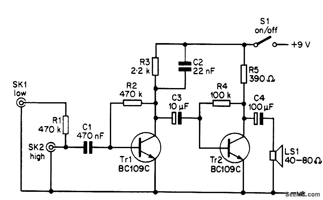
The CW filter is connected between the headphone or loudspeaker socket or terminal strip of your receiver and either the headphones or an external loudspeaker. The output of the receiver should have an intpedance of 8Ω or more. As the circuit provides unity gain at pass frequencies and a low-impedance output, there should be no problems with mismatching when the filter is in use. The frequency response of the circuit peaks at approximately 800 Hz, and the -6-dB bandwidth is about 300 Hz or so. The 0-dB points occur at about 350 Hz and 2 kHz. This is sufficient to normally give a substantial reduction in adjacent-channel interference, but the response is not so narrow and peaky that using the receiver with the filter in the circuit becomes difficult, as the wanted signal tends to drift out of the passband and become lost.
Reprinted Url Of This Article:
http://www.seekic.com/circuit_diagram/Basic_Circuit/Filter_Circuit/SW_RECEIVER_CW_FILTER.html
Print this Page | Comments | Reading(3)

Article Categories
power supply circuit
Amplifier Circuit
Basic Circuit
LED and Light Circuit
Sensor Circuit
Signal Processing
Electrical Equipment Circuit
Control Circuit
Remote Control Circuit
A/D-D/A Converter Circuit
Audio Circuit
Measuring and Test Circuit
Communication Circuit
Computer-Related Circuit
555 Circuit
Automotive Circuit
Repairing Circuit
Code: