Filter Circuit
Typical Application Circuit of M50142P IC
Published:2011/5/18 2:28:00 Author:Michel | Keyword: Typical Application Circuit, IC | From:SeekIC
Typical Application Circuit
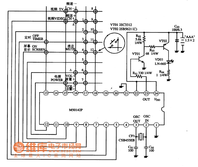
Typical Application circuit of infrared remote control composed of IM50142P IC is showed as above.Picture:Typical Application Circuit of M50142P IC
Notice:This circuit is the original picture of remote control infrared-emitter so the resistor sign hasn't been modified.
Note:VT01and VT02 are direct coupling system drive circuits.Supply voltage reachs the groundafter it passesinfrared-emitting diode,VD01, and resistance, RO4, when VT02 tube short-circuits.At this time,infrared-emitting diode shines but without any information in infrared light so the remote control is invalid.
Reprinted Url Of This Article:
http://www.seekic.com/circuit_diagram/Basic_Circuit/Filter_Circuit/Typical_Application_Circuit_of_M50142P_IC.html
Print this Page | Comments | Reading(3)

Article Categories
power supply circuit
Amplifier Circuit
Basic Circuit
LED and Light Circuit
Sensor Circuit
Signal Processing
Electrical Equipment Circuit
Control Circuit
Remote Control Circuit
A/D-D/A Converter Circuit
Audio Circuit
Measuring and Test Circuit
Communication Circuit
Computer-Related Circuit
555 Circuit
Automotive Circuit
Repairing Circuit
Code: