
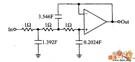
Filter Circuit
Index 21
Pin Function Circuit of M50143-006P IC
Published:2011/5/16 10:11:00 Author:Michel | Keyword: Pin Function Circuit, IC
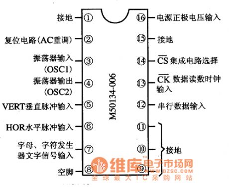
Functions and Features
There are M50143-006P IC's clock oscillator circuit,serial data interface circuit,line and filed impulse generating circuit and character signal generating circuit etc.
Pins' Functions and Data
M50143-006P IC adopts 16 pins dual inline type packaging and its pins' functions are showed as above.
Picture:Pins' Functions of M50143-006P
(View)
View full Circuit Diagram | Comments | Reading(983)
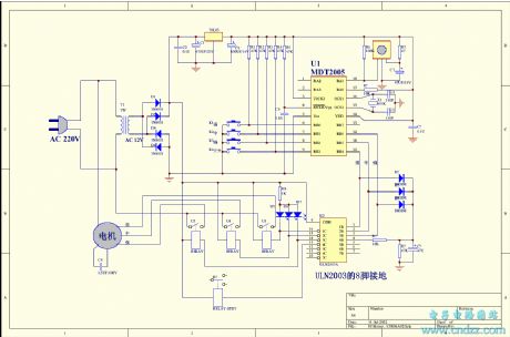
CCU-FDTV-06 single chip microcomputer integrated circuit diagram
Published:2011/5/11 3:31:00 Author:Fiona | Keyword: single chip microcomputer
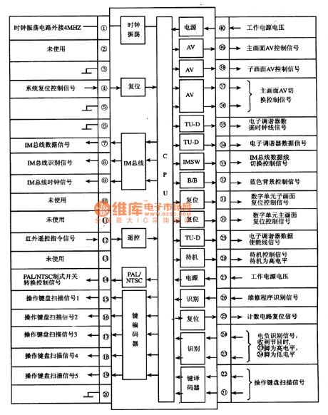
CCUFDTV06 is a single chip microcomputer integrated circuits.Iti (View)
View full Circuit Diagram | Comments | Reading(765)
LC active filter circuit diagram
Published:2011/5/12 20:43:00 Author:Nicole | Keyword: active filter, LC
View full Circuit Diagram | Comments | Reading(1166)
universal single and dual power supply quad op-amp circuit
Published:2011/5/9 2:00:00 Author:John | Keyword: quad op-amp

LM324 is a high-gain quad op-amp, which has four modules inside. Both single power and dual power supply are available for operating. It can work under a rather wide range of working power supply voltage. A very small Supply Current is needed. Input bias current is with temperature compensation performance, so no external frequency compensation components are needed. Amplifier LM324 can be applied in conversion amplifiers, DC gain units and universal op-amp circuits for many applications. And it also can be used directly as interface circuit for a variety of logic circuits and other low-pressure systems. Direct models or substitutions can be LMl24、CFl24MD、CF224LD、CFl24MJ、CF224LJ、CF324CJ and CF324CP and so on. The circuit shown above is the situation that LM324 is used as a dual-threshold voltage comparator.
(View)
View full Circuit Diagram | Comments | Reading(1185)
C271AD single-chip micro-computer communication integrated circuit diagram
Published:2011/5/10 1:16:00 Author:Fiona | Keyword: single-chip micro-computer communication
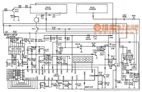
C271AD is a single-chip micro-computer communication integrated circuit. It's widely used in wireless phones and other communication devices.
1. Features
C271AD integrated circuit's in-circuit is mainlyformed by the key position pulse generator circuit, the key instruction encoding circuit, the clock oscillation circuit, two-tone and pulse signal processing circuit,pulse dialing rate intermittent selection circuit,dial-up mode selection circuit, hands-free control circuit, squelch Control circuit etc.
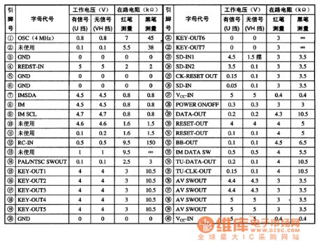
2. pin functions and data
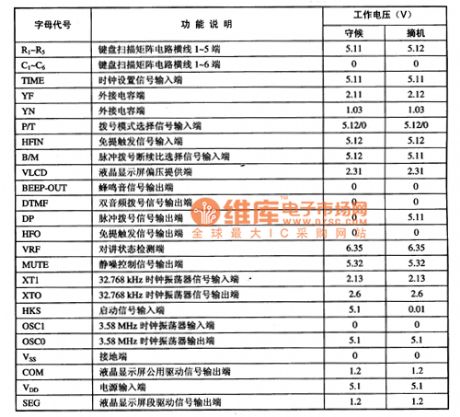
C271AD related pin letter designations, function descriptions and data are listed in Table 1.
Table 1 C271AD integrated circuit's pin functions and data
3. Typical application circuit
the control system typical application circuit which isformed by the C271AD integrated circuit is shown in Figure 1.
Figure 1 The typical application circuit of the C271AD integrated circuit
(View)
View full Circuit Diagram | Comments | Reading(1518)
universal single-supply dual operational amplifier circuit
Published:2011/5/10 23:07:00 Author:John | Keyword: single-supply, dual operational amplifier
(View)
View full Circuit Diagram | Comments | Reading(887)
Universal Dual Power Dual op-amp circuit
Published:2011/5/10 23:07:00 Author:John | Keyword: Dual Power, Dual op amp

Operational amplifiers CF1458 series are amplifiers with high performance dual op amp, whose electrical performance is the same with that of the amplifier /-A747. But the arrangement of pin for these series is different from each other.The features of these series are listed in the following. No external frequency compensation components are needed. And the amplifiers are provided with short circuit protection and the ability to offset voltage to zero. Besides, there is a wide input voltage range for differential mode and common mode. It has low power consumption and no obstruction. Substitutions or direct models can be amplifiers CF1558MT, CF1458CT, CF1558NMT, CF1458NCT, CF1558SMT, CF1458SCT, CF1558MD, CFl458CD, CFl558MJ, CFl458cJ, CFl458CP, CFl558NMD, Fl458NCD, CFl558SMJ, CFl458SCJ, CFl458SCP, CFl558SMD and so on. Amplifiers CFl458N and CFl558N are able to work with low noise. And amplifiersCFl458S and CFl558S can work with high conversion rate. (View)
View full Circuit Diagram | Comments | Reading(927)
Ordinary filter circuit diagram
Published:2011/5/10 2:43:00 Author:Nicole | Keyword: filter
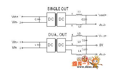
In the ripple and noise susceptible circuit, it can add a filter to DC/DC input terminal and output terminal, it can reduce the ripple and noise. It can absorb the peak voltage of input terminal by importing additional capacitance, it also can store energy and keep voltage stable, The output ripple can be reduced by exporting additional capacitance, the capacitance value too large or ESR too low will easily cause start up problems; if it requires very low ripple, it can adopt LC filtering network or use power module with low ripple output.
(View)
View full Circuit Diagram | Comments | Reading(1292)
High precision remote temperature measurement circuit
Published:2011/5/7 13:07:00 Author:John | Keyword: reemote temperature measurement circuit
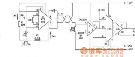
Precision temperature measurement circuit composed of ISO120 and XTR101 is mainly used in remote temperature measurement with a high temperature measurement accuracy. It can also be used for situations with strong noise. ISO120 is a new isolation amplifier, which is designed through the duty factor modulation / demodulation technology. Isolation layer is a two-matched lpF differential capacitor. Digital signals are transmitted. Transmittion of digital signal will not affect the integrity of signals caused by the isolated components. It also has a rather good high-frequency transient performance. Figure shows precision temperature measurement circuit constituted by ISO120 and XTR101. Low temperature drift XTR101 is a 4 ~ 20mA transmitter, and RTD is a thermal resistance. Circuit parameters can guarantee the output current at 4mA in the low temperature end and at 20mA in the high temperature end. Twisted pair will transforme the current to INA105. The current will be converted into electrical signals, then be output through ISO120. (View)
View full Circuit Diagram | Comments | Reading(1234)
input end zero circuit
Published:2011/5/8 2:51:00 Author:John | Keyword: input end zero circuit
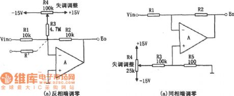
Figure (a) is a relatively simple circuit, which uses the input resistors R1 and feedback resistor R2 as one part of the attenuation, together with the resistor R3 at the inverting input in order to generate a variable offset voltage. The voltage is divied from the R3 and R1 ∥ R2. ± 15V power supply is connected at both ends of the potentiometer R4. And the partial pressure ratio is about 1000 / 1. So the offset voltage can be ranged within ± 15mV . For Figure (a), the general formul for calculating adjustment range of the offset voltage is:
offset voltage range = ± VD • [(R1 ∥ R2) / R3] (± VD = ± 15V)
When there are multiple input signals on the the reverse side, the offset voltage ranges just as shown in virtual display line of Figure (a).
multiple input offset voltage range = ± VD [(R1 ∥ R2 ∥ Rl ') / R3] (± VD = ± l5V) Comparing the above two equations, the former one is clearly with a wider voltage range of adjustment voltage. To increase the voltage adjustment range of the latter one, it is suggested to appropriately change the size of resistor R5.
Figure (b) shows that this circuit has a wide range of applications, because the adjustment voltage has nothing to do with feedback components. And adjustment voltage is set in both input ends, avoiding the winning stream signaling pathways. In this circuit, R3 and R5 of the resistance (100kΩ, 100Ω) form 1000 / I of the voltage divider. And R5 will get adjustment range of ± 15mV offset voltage at both ends. When R3 and R5 are set at other values, adjustment range of offset voltage can be determined by the following formula: offset voltage adjustment range = ± VD • (R5/R3) (± VD = ± l5V)
There is few requirements for resistance of resistors R3 and R5. In fact, it is better to choose the resistance of resistor R5 below 1kΩ. (View)
View full Circuit Diagram | Comments | Reading(908)
high performance release in pairs circuit
Published:2011/5/7 13:16:00 Author:John | Keyword: high performance release in pairs circuit
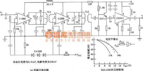
The firgue shows the high performance release in pairs circuit. It is applicable for particularly strict release in pairs circuit. And it also can be used in general release in a receiver. Advantages for these circuits are high gain, excellent load capacity, good reliability and simple circuit. It also has a wide range for AGG. When used in pairs, consistency of amplitude frequency and phase frequency can be helpful to achieve very high targets. (View)
View full Circuit Diagram | Comments | Reading(664)
photodiode isolation amplifier circuit
Published:2011/5/7 11:30:00 Author:John | Keyword: photodiode, Isolation amplifier circuit
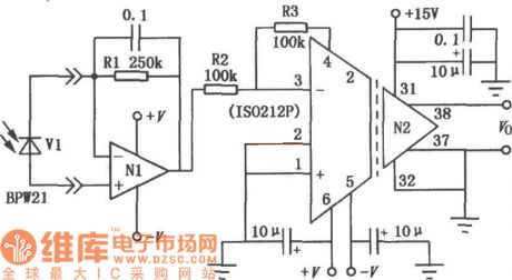
Photodiode isolation amplifier circuit makes the use of photodiode in order to provide reliable isolation between signal channel and power channel. IS0212P is a transformer coupled isolation amplifier circuit in small size and low cost. The inside chip uses two small but high-efficiency toroidal transformers, providing reliable isolation between signal channel and power channel. The firgue above shows the typical application in Photodetector. Photodiode BPW21 is parallelly set in two input ends of the OPAl28 (N1), causing the composition of I / U resistor gain. It adopts the amplifier feedback resistor. The selected op-amp with high impedance and low bias current aims to reduce the influence on photoelectric detection accuracy of the amplifier bias current. Amplifier OPA128 is powered by the ± V isolated power inside of the isolation amplifier ISO212P. Voltage signal of 1 / U is transformed by l00kΩ resistor into the inverting end of the input amplifier inside of IS0212P. Since the feedback resistor is R3 is also due to 100kΩ, the gain is -l. (View)
View full Circuit Diagram | Comments | Reading(2289)
Capacitor fourth-order low-pass filter circuit diagram
Published:2011/5/4 22:42:00 Author:Rebekka | Keyword: Fourth-order low-pass capacitor filter
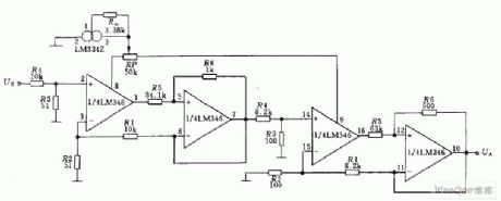
Capacitor fourth-order low-pass filter circuit is shown as below. The circuit uses an LM348 op amp four high-level low-pass filter circuit. For example, fc = 20KHz, filter transmission coefficient is Ho = 1, Q01 = 0.514, Q02 = 1.306. Because the count of band-pass amplification factor is the same with the four amplifiers. So it is enough to equip with a current source (LM334Z). You can have a precise adjustment by potentiometer RP. (View)
View full Circuit Diagram | Comments | Reading(2092)
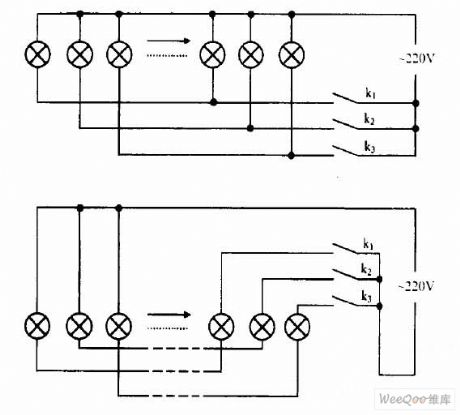
Colored Lights Join Methods Circuit
Published:2011/4/23 3:57:00 Author:Joyce | Keyword: ColoredLights, Join Methods,
View full Circuit Diagram | Comments | Reading(725)
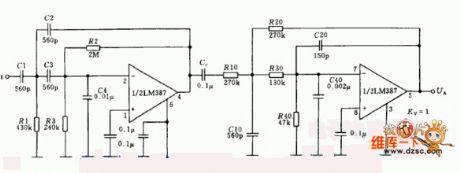
Voice filter circuit used lm387
Published:2011/3/27 21:49:00 Author:may | Keyword: Voice filter
View full Circuit Diagram | Comments | Reading(1597)
MP3 Player Power Filter Circuit
Published:2011/3/22 3:48:00 Author:may | Keyword: MP3 Player, Power Filter
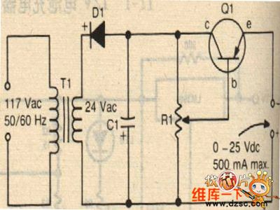
MP3 Player Power Filter Circuit is shown in the following picture:
(View)
View full Circuit Diagram | Comments | Reading(1003)
| Pages:21/21 At 2021 |
Circuit Categories
power supply circuit
Amplifier Circuit
Basic Circuit
LED and Light Circuit
Sensor Circuit
Signal Processing
Electrical Equipment Circuit
Control Circuit
Remote Control Circuit
A/D-D/A Converter Circuit
Audio Circuit
Measuring and Test Circuit
Communication Circuit
Computer-Related Circuit
555 Circuit
Automotive Circuit
Repairing Circuit