Basic Circuit
Frequency / voltage conversion circuit composed of transistor
Published:2011/7/6 20:07:00 Author:Lucas | Keyword: Frequency conversion, voltage conversion, transistor | From:SeekIC
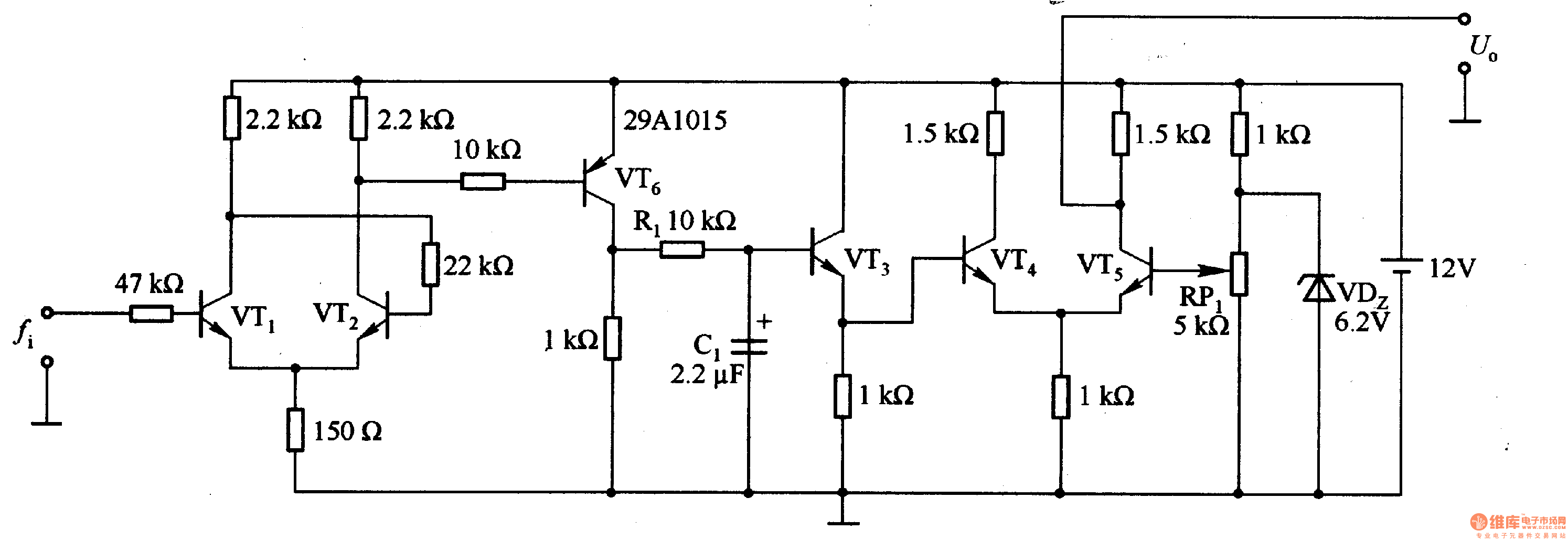
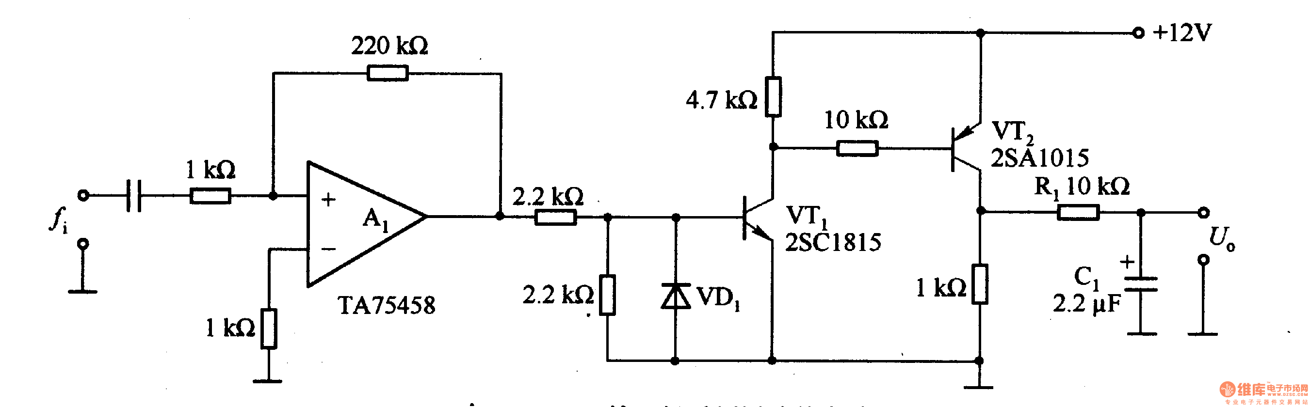
In the Figure 1-19 (a), the VTl and VT2 form the Schmidt circuit to shape the input waveform; Rl and C1 form the integration circuit; VT3 is the buffer circuit; the VT4 and VT5 form the amplifier circuit. The main features of the circuit is that it has high noise immunity, adjustable signal level and circuit constants, and it is the basic frequency / voltage conversion circuit. In the Figure 1-19 (b), the output mostly uses operational amplifier, and the output part uses the frequency / voltage conversion circuit composed of transistors.
Reprinted Url Of This Article:
http://www.seekic.com/circuit_diagram/Basic_Circuit/Frequency___voltage_conversion_circuit_composed_of_transistor.html
Print this Page | Comments | Reading(3)

Article Categories
power supply circuit
Amplifier Circuit
Basic Circuit
LED and Light Circuit
Sensor Circuit
Signal Processing
Electrical Equipment Circuit
Control Circuit
Remote Control Circuit
A/D-D/A Converter Circuit
Audio Circuit
Measuring and Test Circuit
Communication Circuit
Computer-Related Circuit
555 Circuit
Automotive Circuit
Repairing Circuit
Code: