Basic Circuit
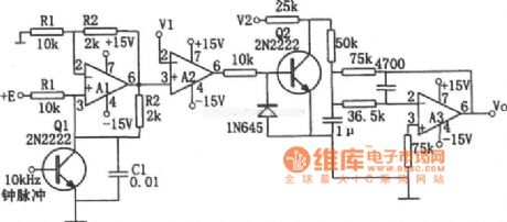
LM101, HA2-2520 multiplication circuit diagram
Published:2011/8/19 1:19:00 Author:Jessie | Keyword: multiplication | From:SeekIC

As shown in figure is multiplication circuit, A1 forms voltage controlled current source, A2 forms voltage comparator, A3 forms active low-pass filter. When time constant R1C1 equals to the clock pulse cycle, the relationship between input and output is: Vo=-V1V2/E. If make E=1V, thereare Vo=-V1V2, V1 and V2 required to be positive and limited in 10V, the V1 is slightly below E. Resistors R1, R2 and capacitor C1 require touse thecomponents withgoodtemperature stability. A1is HA2-2520, A2, A3choose LM101A.
Reprinted Url Of This Article:
http://www.seekic.com/circuit_diagram/Basic_Circuit/LM101_HA2_2520_multiplication_circuit_diagram.html
Print this Page | Comments | Reading(3)

Article Categories
power supply circuit
Amplifier Circuit
Basic Circuit
LED and Light Circuit
Sensor Circuit
Signal Processing
Electrical Equipment Circuit
Control Circuit
Remote Control Circuit
A/D-D/A Converter Circuit
Audio Circuit
Measuring and Test Circuit
Communication Circuit
Computer-Related Circuit
555 Circuit
Automotive Circuit
Repairing Circuit
Code: