Basic Circuit
Pulse width / voltage conversion circuit composed of TL082
Published:2011/7/5 8:16:00 Author:Lucas | Keyword: Pulse width , voltage conversion | From:SeekIC
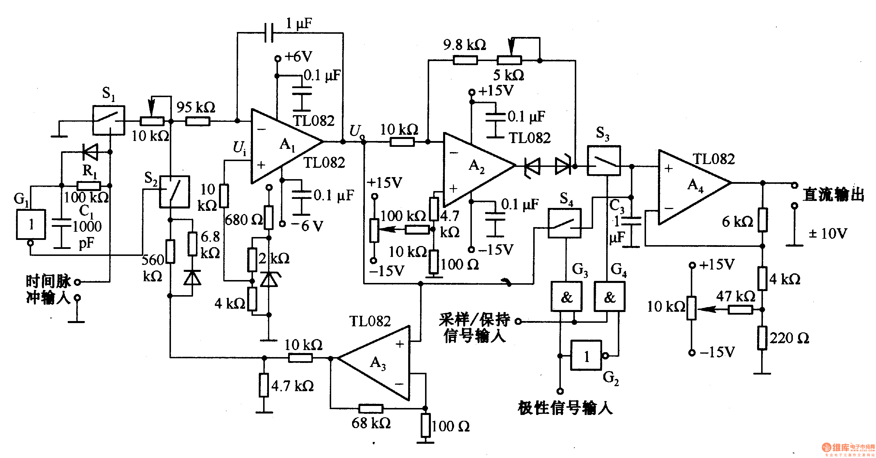
This is the pulse width (time) / voltage conversion circuit, according to the diagram component parameters, it can convert 0.1 S pulse width into 10V output voltage. When time pulse input end is added input conversion pulse, the analog switch Sl is disconnected, and S2 is connected, then Al integrator output is OV. This state has been maintained to be increased the input pulse. After added pulse, Sl is turned on and S2 is off, and the feedback loop is cut off, then Al makes integral on the reference voltage, and its output reduces in the negative direction and changes into low level at the end of integral. If the input pulse goes low, Sl is immediately disconnected.
Reprinted Url Of This Article:
http://www.seekic.com/circuit_diagram/Basic_Circuit/Pulse_width___voltage_conversion_circuit_composed_of_TL082.html
Print this Page | Comments | Reading(3)

Article Categories
power supply circuit
Amplifier Circuit
Basic Circuit
LED and Light Circuit
Sensor Circuit
Signal Processing
Electrical Equipment Circuit
Control Circuit
Remote Control Circuit
A/D-D/A Converter Circuit
Audio Circuit
Measuring and Test Circuit
Communication Circuit
Computer-Related Circuit
555 Circuit
Automotive Circuit
Repairing Circuit
Code: