Basic Circuit
Push-pull Type DC/DC Converter Circuit
Published:2011/7/7 16:20:00 Author:Michel | Keyword: Push-pull Type, DC/DC, Converter Circuit | From:SeekIC
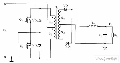
The push-pull type DC/DC converter circuit is shown as above.Among them,transformer T1 acts as isolation and energy transmission.When switch tube Q1 turns on,transformer T1's windings works and it couples with vice side Ns1 winding.When switch tube Q1 turns off,Np1 releases energy to Ns1 and vice versa.The vice edge of rectifier circuit on output end is composed of flow inductor Lo and VD1, VD2.In the circuit design,both ends of switch tube should set RC absorbing circuit to the peak surge which is produced when the switch tube turns off.
Picture:Push-pull Type DC/DC Converter Circuit
Reprinted Url Of This Article:
http://www.seekic.com/circuit_diagram/Basic_Circuit/Push_pull_Type_DC_DC__Converter_Circuit.html
Print this Page | Comments | Reading(3)

Article Categories
power supply circuit
Amplifier Circuit
Basic Circuit
LED and Light Circuit
Sensor Circuit
Signal Processing
Electrical Equipment Circuit
Control Circuit
Remote Control Circuit
A/D-D/A Converter Circuit
Audio Circuit
Measuring and Test Circuit
Communication Circuit
Computer-Related Circuit
555 Circuit
Automotive Circuit
Repairing Circuit
Code: