Basic Circuit
The basic voltage/frequency conversion circuit composed of transistor
Published:2011/7/7 4:25:00 Author:Lucas | Keyword: basic , voltage conversion, frequency conversion , transistor | From:SeekIC
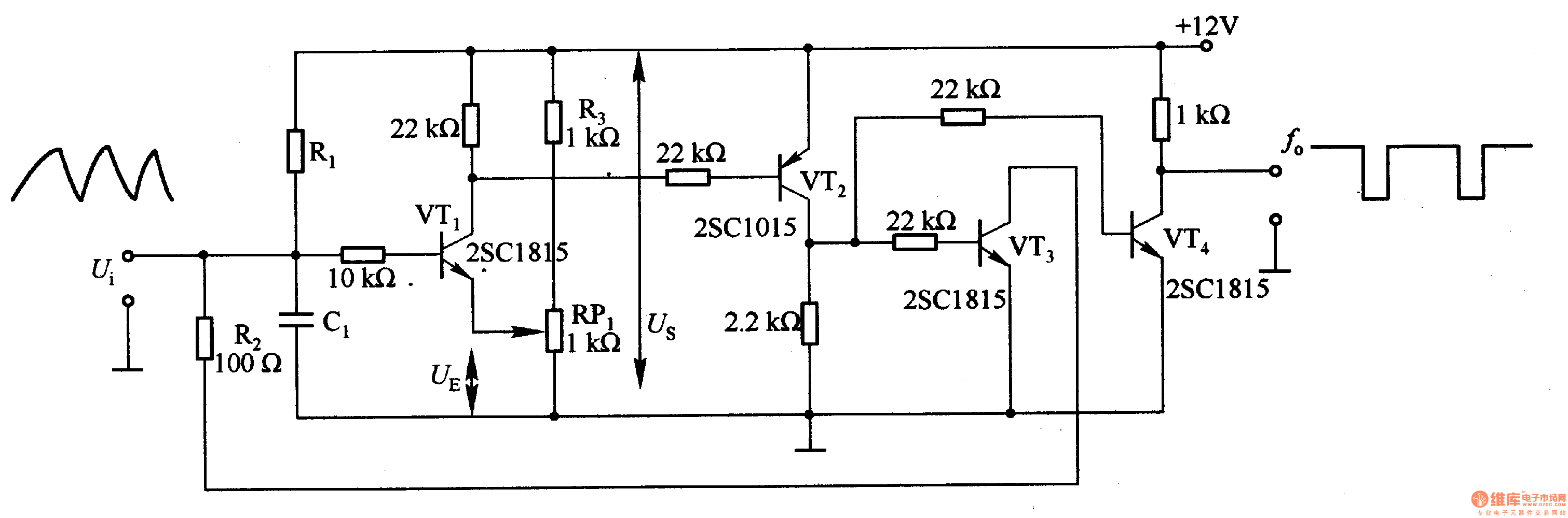
In the circuit, the RlC1 time constant and timing time of control comparator VT1 output are decided by changing set voltage UE. When VTl is turned on, VT2 and VT3 are turned on, then the integration capacitor C1 begins to discharge. R2 can adjust the discharge time constant. When set voltage UE is small, the oscillation frequency increases. In the circuit, VTl, VT3 and VT4 use 2SCl815 or 2SC945, VT2 uses 2SAlO15 or 2SA952.
Reprinted Url Of This Article:
http://www.seekic.com/circuit_diagram/Basic_Circuit/The_basic_voltage_frequency_conversion_circuit_composed_of_transistor.html
Print this Page | Comments | Reading(3)

Article Categories
power supply circuit
Amplifier Circuit
Basic Circuit
LED and Light Circuit
Sensor Circuit
Signal Processing
Electrical Equipment Circuit
Control Circuit
Remote Control Circuit
A/D-D/A Converter Circuit
Audio Circuit
Measuring and Test Circuit
Communication Circuit
Computer-Related Circuit
555 Circuit
Automotive Circuit
Repairing Circuit
Code: