Position: Home > Circuit Diagram > Basic Circuit > The typical application circuit of capacitive sensor signal conditioner CS2001
Basic Circuit
The typical application circuit of capacitive sensor signal conditioner CS2001
Published:2012/10/12 21:43:00 Author:Ecco | Keyword: typical application, capacitive sensor, signal conditioner | From:SeekIC
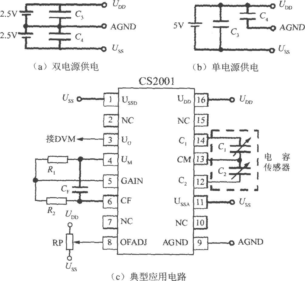
Figure (a) shows the ± 2.5V dual supply wiring diagram, Figure (b) shows a single +5 V power supply wiring diagram. C3, C4 are decoupling capacitors. In the Figure (c), CF is a capacitor for adjusting the bandwidth, RP is a potentiometer for adjusting the gain. CS2001 output voltage is Uo, AGND end leads are followed by digital voltage table ( DVM ).
Reprinted Url Of This Article:
http://www.seekic.com/circuit_diagram/Basic_Circuit/The_typical_application_circuit_of_capacitive_sensor_signal_conditioner_CS2001.html
Print this Page | Comments | Reading(3)

Article Categories
power supply circuit
Amplifier Circuit
Basic Circuit
LED and Light Circuit
Sensor Circuit
Signal Processing
Electrical Equipment Circuit
Control Circuit
Remote Control Circuit
A/D-D/A Converter Circuit
Audio Circuit
Measuring and Test Circuit
Communication Circuit
Computer-Related Circuit
555 Circuit
Automotive Circuit
Repairing Circuit
Code: