Control Circuit
Alternating Current Voltage Multiplier(MC1594) Circuit
Published:2011/7/21 6:54:00 Author:Sue | Keyword: Alternating Current, Voltage, Multiplier | From:SeekIC
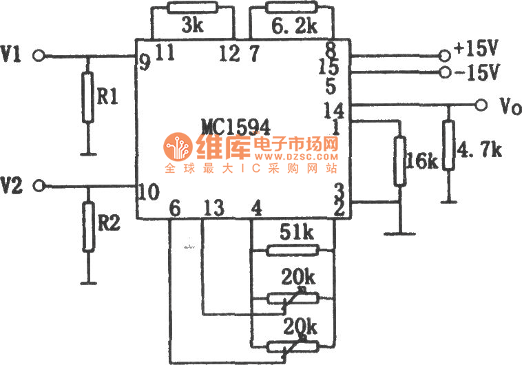
The picture shows the alternating current voltage multiplier circuit. The circuit is composed of MC1594 four-quadrant multiplier .It is very simple but is not very precised. In order to make the circuit work in linearization range, the resistance value of the input terminal's resistor R1 and R2 will be decided by input voltage. R1= V1×6. R2=V2×3. If V1=V2=3V, then R1=18kΩ, R2=9kΩ. When there are different input voltages, R1=52kΩ, R2=30kΩ. But this will slow down the precision and degree of linearity. The relation between the input and output is: Vo=V1V2/10.
Reprinted Url Of This Article:
http://www.seekic.com/circuit_diagram/Control_Circuit/Alternating_Current_Voltage_MultiplierMC1594_Circuit.html
Print this Page | Comments | Reading(3)

Article Categories
power supply circuit
Amplifier Circuit
Basic Circuit
LED and Light Circuit
Sensor Circuit
Signal Processing
Electrical Equipment Circuit
Control Circuit
Remote Control Circuit
A/D-D/A Converter Circuit
Audio Circuit
Measuring and Test Circuit
Communication Circuit
Computer-Related Circuit
555 Circuit
Automotive Circuit
Repairing Circuit
Code: