Control Circuit
Digitally_controlled_threshold_detector
Published:2009/7/24 22:16:00 Author:Jessie | From:SeekIC
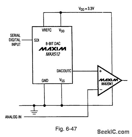
Figure 6-47 shows a MAX941 comparator combined with a MAX512 DAC to form a digitally controlled threshold detector. The analog signal to be compared is applied directly to the inverting input of the MAX941. The threshold point is set by the DAC output applied to the noninverting input. In turn, the DAC output is set by the serial digital input. As a result, the threshold can be set in eight discrete steps (depending on the serial input). MAXIM NEW RELEASES DATA BOOK, 1995, P. 3-69.
Reprinted Url Of This Article:
http://www.seekic.com/circuit_diagram/Control_Circuit/Digitally_controlled_threshold_detector.html
Print this Page | Comments | Reading(3)

Article Categories
power supply circuit
Amplifier Circuit
Basic Circuit
LED and Light Circuit
Sensor Circuit
Signal Processing
Electrical Equipment Circuit
Control Circuit
Remote Control Circuit
A/D-D/A Converter Circuit
Audio Circuit
Measuring and Test Circuit
Communication Circuit
Computer-Related Circuit
555 Circuit
Automotive Circuit
Repairing Circuit
Code: