Control Circuit
Motor protector 9
Published:2011/6/27 21:12:00 Author:Nicole | Keyword: Motor, protector | From:SeekIC

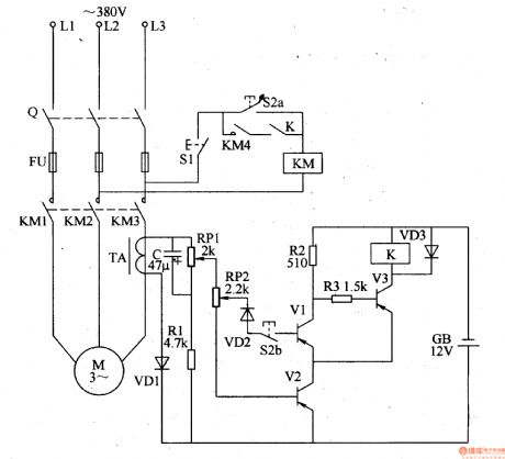
This motor protector circuit is composed of starting control circuit, phase failure detection circuit and protection implement circuit, it is shown in the figure 8-45.
The starting control circuit is made of starter button S2 and stop button S1.
The phase failure detection circuit consists of current mutual inductor TA, rectifier diode VD1, resistor R1, capacitor C and potentiometer RP1, RP.
The protection implement circuit is composed of transistors V1-V3, relay K and AC contactor KM.
V1's sensitivity can be changed by adjusting RP1 and RP2.
Reprinted Url Of This Article:
http://www.seekic.com/circuit_diagram/Control_Circuit/Motor_protector_9.html
Print this Page | Comments | Reading(3)

Article Categories
power supply circuit
Amplifier Circuit
Basic Circuit
LED and Light Circuit
Sensor Circuit
Signal Processing
Electrical Equipment Circuit
Control Circuit
Remote Control Circuit
A/D-D/A Converter Circuit
Audio Circuit
Measuring and Test Circuit
Communication Circuit
Computer-Related Circuit
555 Circuit
Automotive Circuit
Repairing Circuit
Code: