Control Circuit
PIN diode with band-pass filter switch circuit
Published:2011/6/19 10:56:00 Author:John | Keyword: diode, band-pass filter, switch | From:SeekIC
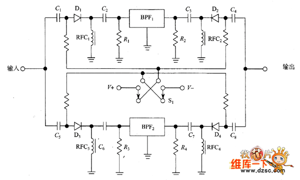
The picture shows how to choose a variety of band-pass filters in the circuit, for which only the DC signal lines are between the panel and the circuit. Input end and output end shown in the figure all have PIN diode. The PIN diodes are all powered by +12 V selected by the switch S1 or-12V DC power supply. When the switch is in the position shown, +12 V powers filter 1’s switch and the filter 1 works. When the switch is in the opposite position, the other filters work. This method can also be used for receiver’s front-end or local oscillator in order that different frequency bands can be selected for different LC components.
figure: PIN diode with band-pass filter switch circuit
Reprinted Url Of This Article:
http://www.seekic.com/circuit_diagram/Control_Circuit/PIN_diode_with_band_pass_filter_switch_circuit.html
Print this Page | Comments | Reading(3)

Article Categories
power supply circuit
Amplifier Circuit
Basic Circuit
LED and Light Circuit
Sensor Circuit
Signal Processing
Electrical Equipment Circuit
Control Circuit
Remote Control Circuit
A/D-D/A Converter Circuit
Audio Circuit
Measuring and Test Circuit
Communication Circuit
Computer-Related Circuit
555 Circuit
Automotive Circuit
Repairing Circuit
Code: