Protection Circuit
The centralized controller of drainage and irrigation pumping station Two
Published:2011/8/8 21:43:00 Author:Felicity | Keyword: centralized controller, drainage and irrigation pumping station | From:SeekIC
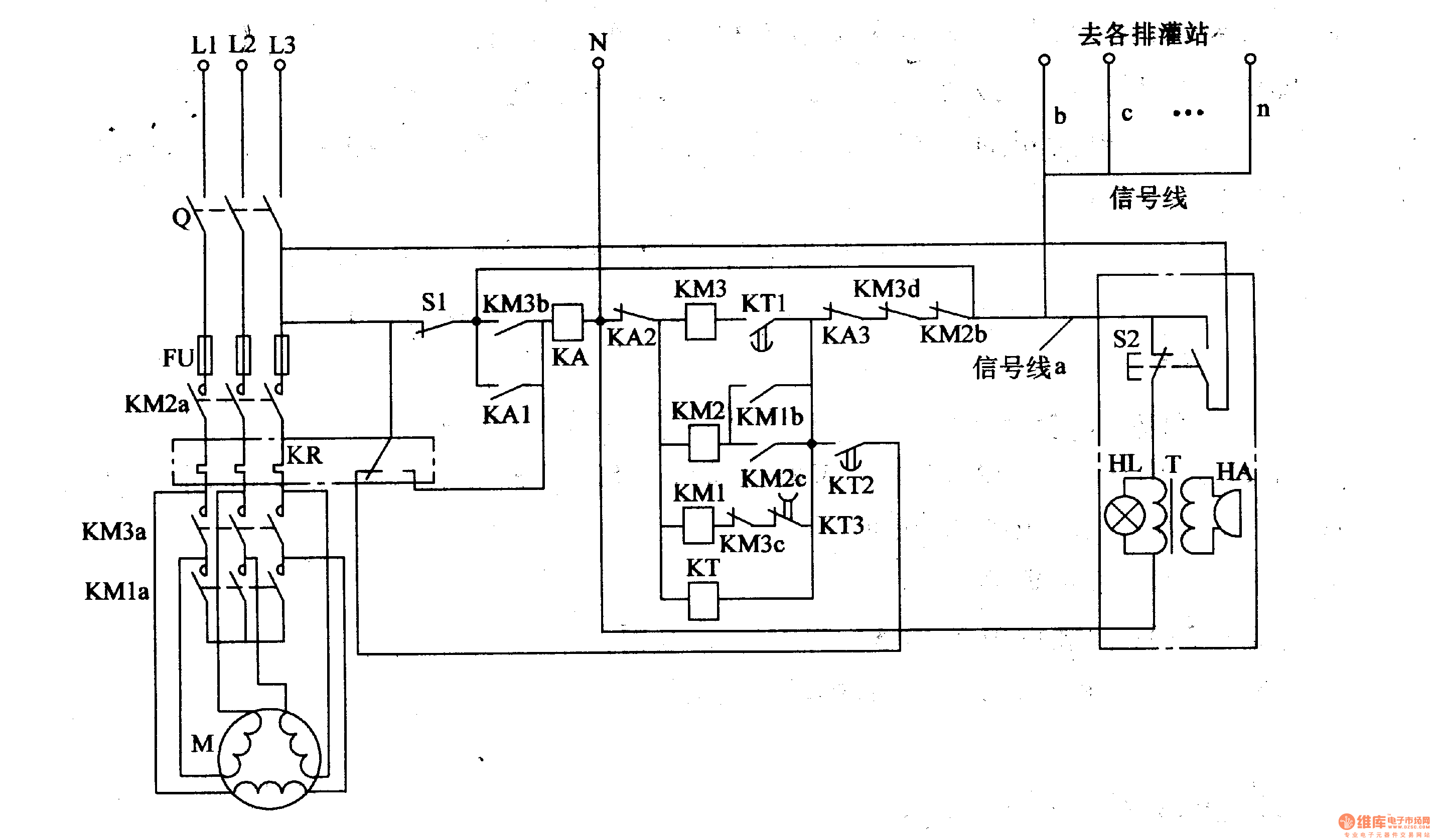
First turn Q on, and press S2 in the control room or S1 in the irrigation and drainage machine room. Then the phase voltage of L1 goes through the normally open contact of S2, signal line a, normally close contact KM2b, KM3b, KA3, KT, AKA2 to null line to make up current circuit. And KT turns on and KM1, KM2 closes in succession and the pump motor starts as Y step-down start. When it need to stop , pressing S2 or S1 again to make KA turn on, the normally open contact of KA1 close ,then the normally open contact KA2 and M3 turns off to make KM2 and KM3 release and the pump motor stops.
Reprinted Url Of This Article:
http://www.seekic.com/circuit_diagram/Control_Circuit/Protection_Circuit/The_centralized_controller_of_drainage_and_irrigation_pumping_station_Two.html
Print this Page | Comments | Reading(3)

Article Categories
power supply circuit
Amplifier Circuit
Basic Circuit
LED and Light Circuit
Sensor Circuit
Signal Processing
Electrical Equipment Circuit
Control Circuit
Remote Control Circuit
A/D-D/A Converter Circuit
Audio Circuit
Measuring and Test Circuit
Communication Circuit
Computer-Related Circuit
555 Circuit
Automotive Circuit
Repairing Circuit
Code: