Switch Control
HIGH_VOLTAGE_AC_SWITCHER
Published:2009/7/8 22:13:00 Author:May | From:SeekIC
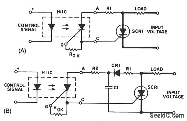
A basic circuit to trigger an SCR is shown in Fig. 67-1A. This circuit has the disadvantage that the blocking voltage of the photoncoupler output device determines the circuit-blocking voltage, irrespective of higher main SCR capability.
Adding capacitor C1 to the circuit, as shown in Fig. 67-1B, will reduce the dV/dt seen by the photon-coupler output device. The energy stored in C1, when discharged into the gate of SCR1, will improve the di/dt capability of the main SCR.
Using a separate power supply for the coupler adds flexibility to the trigger circuit; it removes the limitation of the blocking voltage capability of the photon-coupler output device. The flexibility adds cost and more than one power supply nftght be necessary for multiple SCRs if no common reference points are available.
Reprinted Url Of This Article:
http://www.seekic.com/circuit_diagram/Control_Circuit/Switch_Control/HIGH_VOLTAGE_AC_SWITCHER.html
Print this Page | Comments | Reading(3)

Article Categories
power supply circuit
Amplifier Circuit
Basic Circuit
LED and Light Circuit
Sensor Circuit
Signal Processing
Electrical Equipment Circuit
Control Circuit
Remote Control Circuit
A/D-D/A Converter Circuit
Audio Circuit
Measuring and Test Circuit
Communication Circuit
Computer-Related Circuit
555 Circuit
Automotive Circuit
Repairing Circuit
Code: