Control Circuit
The multi-functional portable dual-way alarm circuit
Published:2011/7/6 8:47:00 Author:qqtang | Keyword: multi-functional, portable, dual-way alarm | From:SeekIC

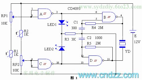
This circuit consists of two parts, the upper limit alarm function is composed of A, B, R4 and C1, and C, D, R5 and C2 form the lower limit alarm function, see as figure 1. Usually, there are two alarm spots, the upper and lower, which are fixed in RP1 and RP2 respectively, which make the input terminals of A and C both in a high LEV, and both of them output a low LEV so the oscillators stop. When it is too hot outside, the resistance of the thermistor is falling down, which makes A output a high LEV, B is starting to oscillate, and the piezoelectric pottery chip YD is generating the bumming sound of high frequency. At the same time, LED1 is glowing, indicating that the temperature is too high.
Reprinted Url Of This Article:
http://www.seekic.com/circuit_diagram/Control_Circuit/The_multi_functional_portable_dual_way_alarm_circuit.html
Print this Page | Comments | Reading(3)

Article Categories
power supply circuit
Amplifier Circuit
Basic Circuit
LED and Light Circuit
Sensor Circuit
Signal Processing
Electrical Equipment Circuit
Control Circuit
Remote Control Circuit
A/D-D/A Converter Circuit
Audio Circuit
Measuring and Test Circuit
Communication Circuit
Computer-Related Circuit
555 Circuit
Automotive Circuit
Repairing Circuit
Code: