Control Circuit
The seeder channel block alarm (2)
Published:2011/7/23 22:05:00 Author:qqtang | Keyword: seeder channel, block alarm | From:SeekIC

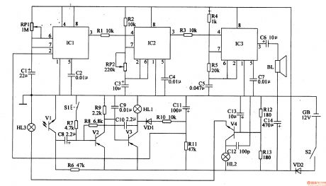
The working principle of the circuitThe seeder channel block alarm circuit consists of the photoelectric control circuit, single steady circuit, 1HZ multi-resonance oscillator, 1KHZ multi-resonance oscillator phase indicator circuit, see as figure 4-104.
The photoelectric control circuit consists of the indicators HL1 and HL3, transistors V2 and V3, resistors R6-R11, capacitors C8-C11, diode VD1 and reset key S1.The astable circuit consists of the potentiometer RP1, capacitors C1 and C2, time-base integrated circuit IC1.
Reprinted Url Of This Article:
http://www.seekic.com/circuit_diagram/Control_Circuit/The_seeder_channel_block_alarm_2.html
Print this Page | Comments | Reading(3)

Article Categories
power supply circuit
Amplifier Circuit
Basic Circuit
LED and Light Circuit
Sensor Circuit
Signal Processing
Electrical Equipment Circuit
Control Circuit
Remote Control Circuit
A/D-D/A Converter Circuit
Audio Circuit
Measuring and Test Circuit
Communication Circuit
Computer-Related Circuit
555 Circuit
Automotive Circuit
Repairing Circuit
Code: