Control Circuit
△ connection electromotor phase loss voltage relay protection circuit
Published:2011/5/30 1:42:00 Author:Christina | Keyword: △ connection, electromotor, phase loss, voltage relay, protection circuit | From:SeekIC
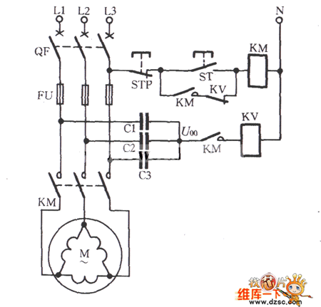
The △ connection electromotor phase loss voltage relay protection circuit is as shown:
For the △ connection electromotor, there need to be a artificial neutral point, we use three equivalent capacitance to form the Y-shape to connect with the electromotor in parallel connection, then we add the protection components at the midpoint of this Y-shape, as the figure shows. When the motor three-phase power is normal operation, the neutral voltage U00 is lower than 10V. If the phase is broken when the electromotor load is operating, the neutral voltage U00 is related with the load, the change range is 10 to 50V. IF we use the DJ131/60CN type voltage relay, the action voltage can be setting in 20 ~ 25V; if the electromotor's load is lower than 50% ~ 60%, the setting voltage is 15 ~ 20V.
Reprinted Url Of This Article:
http://www.seekic.com/circuit_diagram/Control_Circuit/△_connection_electromotor_phase_loss_voltage_relay_protection_circuit.html
Print this Page | Comments | Reading(3)

Article Categories
power supply circuit
Amplifier Circuit
Basic Circuit
LED and Light Circuit
Sensor Circuit
Signal Processing
Electrical Equipment Circuit
Control Circuit
Remote Control Circuit
A/D-D/A Converter Circuit
Audio Circuit
Measuring and Test Circuit
Communication Circuit
Computer-Related Circuit
555 Circuit
Automotive Circuit
Repairing Circuit
Code: