Electrical Equipment Circuit
3_V_33_V_from_three_cells_with_linear_regulation
Published:2009/7/24 23:28:00 Author:Jessie | From:SeekIC
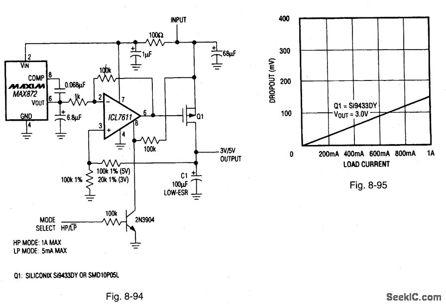
Figure 8-94 shows a MAX872 voltage reference and an ICL7611 micropower op amp connected to form a linear regulator for a 3-V/3.3-V supply. This circuit is particularly effective with NiCad and NiMH batteries. The end of life for such cells is about 1 V, so a linear regulator (with very low dropout) can be used in place of a switching regulator or charge pump. The dropout characteristics for the circuit are shown in Fig. 8-95, and depend primarily on the characteristics of Q1. When the circuit is used with low voltage, such as a three-cell battery, Q1 must have a gate-threshold voltage below that of the lowest battery voltage. For example, the RDS(ON) for the Si9433 is guaranteed at a VGS of 2.7 V. The circuit will operate at input voltages from 3 V to 15 V. The quiescent current (VIN = 6.5 V) is 40 μA when the circuit is operated in the low-power mode, but it increases to 70 μA in the high-power mode. The maximum load current is 1 A in high-power and 5 mA in low-power. The high - and low-power modes are selected by logic at the MODE SELECT input. High-power mode is selected when the input is high. MAXIM BATTERY MANAGEMENT CIRCUIT COLLECTION, 1994, P. 15.
Reprinted Url Of This Article:
http://www.seekic.com/circuit_diagram/Electrical_Equipment_Circuit/3_V_33_V_from_three_cells_with_linear_regulation.html
Print this Page | Comments | Reading(3)

Article Categories
power supply circuit
Amplifier Circuit
Basic Circuit
LED and Light Circuit
Sensor Circuit
Signal Processing
Electrical Equipment Circuit
Control Circuit
Remote Control Circuit
A/D-D/A Converter Circuit
Audio Circuit
Measuring and Test Circuit
Communication Circuit
Computer-Related Circuit
555 Circuit
Automotive Circuit
Repairing Circuit
Code: