Electrical Equipment Circuit
5_V_from_two_to_three_cells_low_cost_micronpower
Published:2009/7/24 23:26:00 Author:Jessie | From:SeekIC
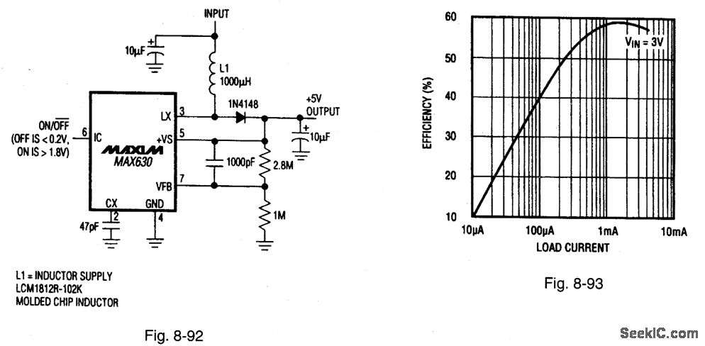
Figure 8-92 shovgs a MAX630 connected to provide a low-cost, micropower 5-V output, with a 1.6-V to 5-V input range. Figure 8-93 shows the efficiency curve. The quiescent current is 160 μA, with a start-up of 2 V, a maximum load current of 5 mA, and a shutdown current of 1 μA. This current is most useful in micropower applications where cost, not efficiency, is the main concern. (Efficiency can be improved by substituting a Schottky rectifier for the 1N4148, and a low-resistance inductor for L1, at the expense of higher cost.) The circuit is boot-strapped (+Vs connected to the +5-V output). In those applications where minimum start-up voltage is essential, connect the +Vs pin directly to the input. Unfortunately, removing the boot-strap connection is done at the expense of low-voltage load-current capability. MAXIM BATTERY MANAGEMENT CIRCUIT COLLECTION, 1994, P. 14.
Reprinted Url Of This Article:
http://www.seekic.com/circuit_diagram/Electrical_Equipment_Circuit/5_V_from_two_to_three_cells_low_cost_micronpower.html
Print this Page | Comments | Reading(3)

Article Categories
power supply circuit
Amplifier Circuit
Basic Circuit
LED and Light Circuit
Sensor Circuit
Signal Processing
Electrical Equipment Circuit
Control Circuit
Remote Control Circuit
A/D-D/A Converter Circuit
Audio Circuit
Measuring and Test Circuit
Communication Circuit
Computer-Related Circuit
555 Circuit
Automotive Circuit
Repairing Circuit
Code: