Electrical Equipment Circuit
Color_TV_chroma_demodulator_with_tint_control
Published:2009/7/21 7:39:00 Author:Jessie | From:SeekIC
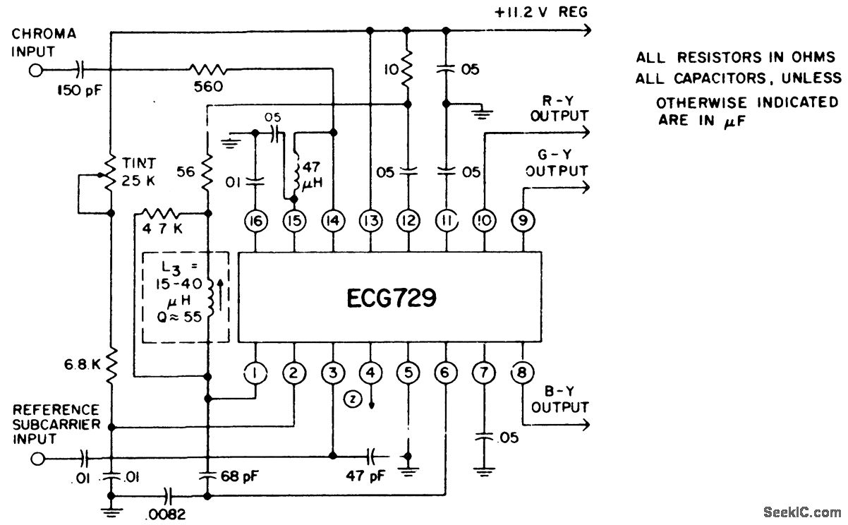
Color TV chroma demodulator with tint control. The color demodulators consist of two sets of balanced detectors that receive their reference subcarrier from the internal demodulator drive amplifiers. The chroma signal input is applied to pin 14. The chroma signal differentially drives the demodulators. The demodulation components are matrixed and DC-shifted in voltage to give R-Y, G-Y and B-Y color difference compo-nents with close DC balance and proper amplitude ratios. When the zener reference element is not used the power supply should be maintained at +11.2 volts (courtesy GTE Sylvania Incorporated).
Reprinted Url Of This Article:
http://www.seekic.com/circuit_diagram/Electrical_Equipment_Circuit/Color_TV_chroma_demodulator_with_tint_control.html
Print this Page | Comments | Reading(3)

Article Categories
power supply circuit
Amplifier Circuit
Basic Circuit
LED and Light Circuit
Sensor Circuit
Signal Processing
Electrical Equipment Circuit
Control Circuit
Remote Control Circuit
A/D-D/A Converter Circuit
Audio Circuit
Measuring and Test Circuit
Communication Circuit
Computer-Related Circuit
555 Circuit
Automotive Circuit
Repairing Circuit
Code: