Other Circuit
Current Limiting Protection Application Cirrcuit Composed of WB705
Published:2011/5/8 6:43:00 Author:Robert | Keyword: Current Limiting, Protection, Application | From:SeekIC
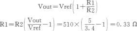

The picture shown below is about the current-limiting protection application cirrcuit with output voltage of 5V and output current of 1.5A which is composed of WB718 multi-port adjustable positive integrated stabilizer. The input voltage of the circuit can be maximum 16.8V and minimum 12.1V. The C1 and C2 are filter capacitors whose value can be choosed based on the current value. The more load current is, the more the capacitor value is required, which would reduce the ripple value of the stabilizer input port. C3 is a compensation capacitor used to prevent the oscillation effects. If the circuit has no oscillation, C3's value can be considerable less. Because C3 is connected directly to the stabilizer internal amplifier through its 7 foot. If its value is too big, that will influence the magnification. C4 can make the variation value of output voltage ΔVout to couple directly to the 6 foot of the stabilizer internal sampling port which can improve ripple rejection ratio. C5 and C6 is the capacitor to output filter wave. R1 and R2 is sampling resistance and they suit for the formula shown below. In its formula, Vref is the stabilizer's base referenced voltage with value of 3.4V. Because Vref has some extent discrete features, it should be a little bigger than the caculation result of R1 when it's chosen to use.
Reprinted Url Of This Article:
http://www.seekic.com/circuit_diagram/Electrical_Equipment_Circuit/Other_circuit/Current_Limiting_Protection_Application_Cirrcuit_Composed_of_WB705.html
Print this Page | Comments | Reading(3)

Article Categories
power supply circuit
Amplifier Circuit
Basic Circuit
LED and Light Circuit
Sensor Circuit
Signal Processing
Electrical Equipment Circuit
Control Circuit
Remote Control Circuit
A/D-D/A Converter Circuit
Audio Circuit
Measuring and Test Circuit
Communication Circuit
Computer-Related Circuit
555 Circuit
Automotive Circuit
Repairing Circuit
Code: