Electrical Equipment Circuit
Voltage_controlled_sine_wave_oscillator
Published:2009/7/25 3:18:00 Author:Jessie | From:SeekIC
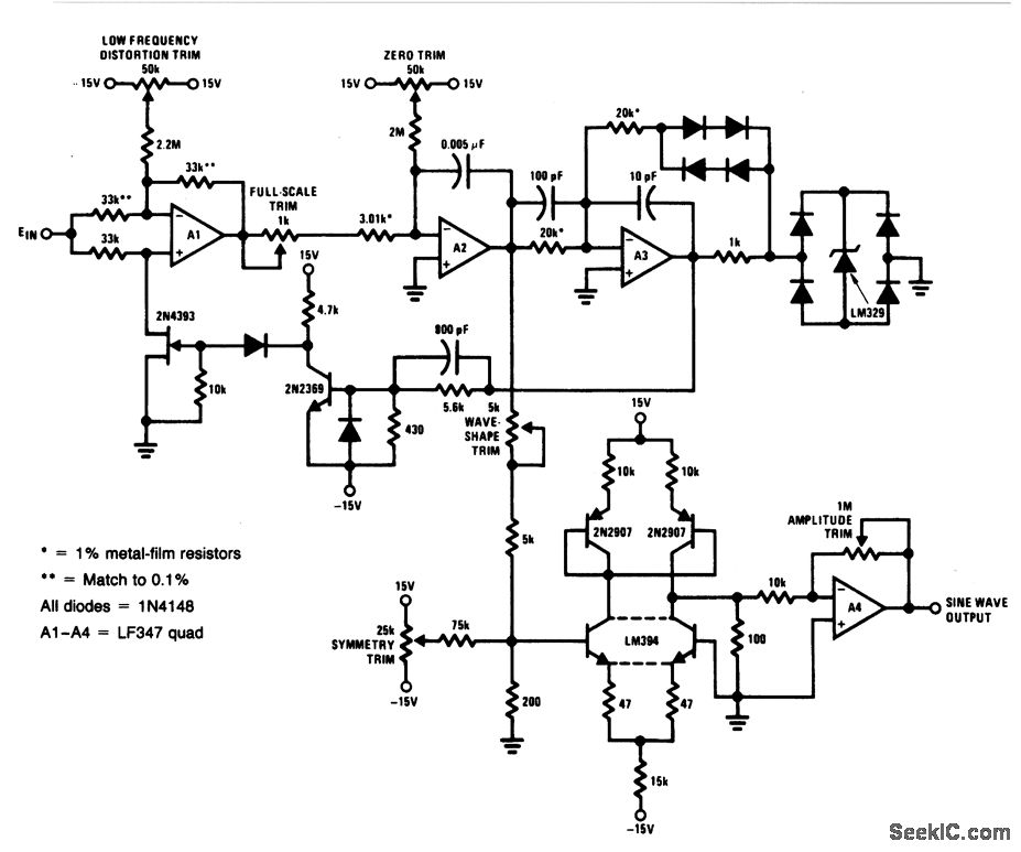
For a 0- to 10-V input, this circuit produces sine-wave outputs of 1 Hz to 20 kHz, with better than 0.2% linearity. Distortion is about 0.4% and the sine-wave output frequency and amplitude settle instantaneously to a step-input change. To calibrate, apply 10 V to the input and adjust the wave-shape trim and symmetry trim for minimum distortion on a distortion analyzer. Next, adjust the input voltage for an output frequency of 10 Hz and trim the low-frequency distortion for minimum indication on the distortion analyzer. Finally, alternately adjust the zero and full-scale pots so that inputs of 500μV and 10 V yield respective outputs of 1 Hz and 20 kHz.
Reprinted Url Of This Article:
http://www.seekic.com/circuit_diagram/Electrical_Equipment_Circuit/Voltage_controlled_sine_wave_oscillator.html
Print this Page | Comments | Reading(3)

Article Categories
power supply circuit
Amplifier Circuit
Basic Circuit
LED and Light Circuit
Sensor Circuit
Signal Processing
Electrical Equipment Circuit
Control Circuit
Remote Control Circuit
A/D-D/A Converter Circuit
Audio Circuit
Measuring and Test Circuit
Communication Circuit
Computer-Related Circuit
555 Circuit
Automotive Circuit
Repairing Circuit
Code: