Position: Home > Circuit Diagram > LED and Light Circuit > IR remote control dimmer light circuit diagram
LED and Light Circuit
IR remote control dimmer light circuit diagram
Published:2011/9/27 1:50:00 Author:Rebekka | Keyword: IR remote control dimmer light | From:SeekIC
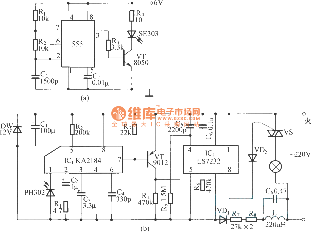
(a) is infrared emission circuit diagram. NE555 circuit generates a 40kHz pulse which is sent by the infrared emission control SE303 after beingamplified by VT. (b) is remote receiver and infrared dimming circuit composed of the KA2184. LS7232 is an integrated dimming circuit.
Reprinted Url Of This Article:
http://www.seekic.com/circuit_diagram/LED_and_Light_Circuit/IR_remote_control_dimmer_light_circuit_diagram.html
Print this Page | Comments | Reading(3)

Article Categories
power supply circuit
Amplifier Circuit
Basic Circuit
LED and Light Circuit
Sensor Circuit
Signal Processing
Electrical Equipment Circuit
Control Circuit
Remote Control Circuit
A/D-D/A Converter Circuit
Audio Circuit
Measuring and Test Circuit
Communication Circuit
Computer-Related Circuit
555 Circuit
Automotive Circuit
Repairing Circuit
Code: