Measuring and Test Circuit
1_MHz_bandpass_filter_insertion_loss_tester
Published:2009/7/17 5:24:00 Author:Jessie | From:SeekIC
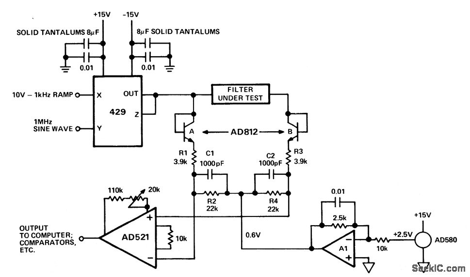
1 MHz bandpass filter insertion-loss tester. The test is performed by sweeping the amplitude of the input signal and comparing the envelopes of the input and output signals, The test signal is produced by modulating a 1 MHz sinusoidal carrier with a 10-volt 1 kHz ramp using a 429 multiplier. The test signal is demodulated by the diode-connected AD812A and network R1-R2-C1.The signal coming out of the filter under test is passed through an identical network consisting of AD812B, R3, R4 and C2. The AD521 compares the two demodulated outputs (courtesy Analog Devices, Inc.).
Reprinted Url Of This Article:
http://www.seekic.com/circuit_diagram/Measuring_and_Test_Circuit/1_MHz_bandpass_filter_insertion_loss_tester.html
Print this Page | Comments | Reading(3)

Article Categories
power supply circuit
Amplifier Circuit
Basic Circuit
LED and Light Circuit
Sensor Circuit
Signal Processing
Electrical Equipment Circuit
Control Circuit
Remote Control Circuit
A/D-D/A Converter Circuit
Audio Circuit
Measuring and Test Circuit
Communication Circuit
Computer-Related Circuit
555 Circuit
Automotive Circuit
Repairing Circuit
Code: