Measuring and Test Circuit
AC_LINE_VOLTAGE_MONITOR
Published:2009/7/16 21:09:00 Author:Jessie | From:SeekIC
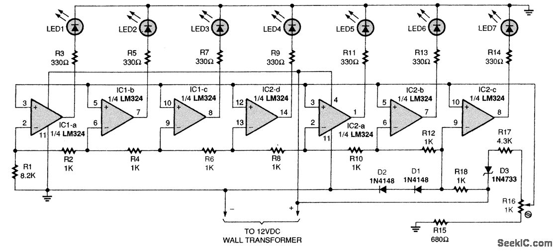
This figure shows the schematic of the ac line-voltage monitor circuit. The circuit receives 12 Vdc from a wall transformer. The circuit is centered around two quad LM324 op-amp ICs (IC1 and IC2) that receive regulated operating power from a clamped portion of the dc supply provided by a 5.1-V zener diode, D3. The op amps drive an LED bar graph, consisting of LED1 through LED7. The op amps receive an adjustable reference voltage from the center contact of potentiometer R16 and an input voltage from the voltage divider, consisting of resistors R1, R2, R4, R6, R8, R10, R12, and R18. Those resistor values were chosen so that the op-amp outputs sequentially turn on and light the LEDs as the ac line voltage, or one-tenth of it, varies from 100 to 132 V. Potentiometer R16 sets the midpoint of the LED bar graph-usually 118 V-which can be shifted, if you like.
Reprinted Url Of This Article:
http://www.seekic.com/circuit_diagram/Measuring_and_Test_Circuit/AC_LINE_VOLTAGE_MONITOR.html
Print this Page | Comments | Reading(3)

Article Categories
power supply circuit
Amplifier Circuit
Basic Circuit
LED and Light Circuit
Sensor Circuit
Signal Processing
Electrical Equipment Circuit
Control Circuit
Remote Control Circuit
A/D-D/A Converter Circuit
Audio Circuit
Measuring and Test Circuit
Communication Circuit
Computer-Related Circuit
555 Circuit
Automotive Circuit
Repairing Circuit
Code: