Measuring and Test Circuit
LOW_VOLTAGE_DETECTOR
Published:2009/6/25 21:34:00 Author:May | From:SeekIC
Circuit Notes
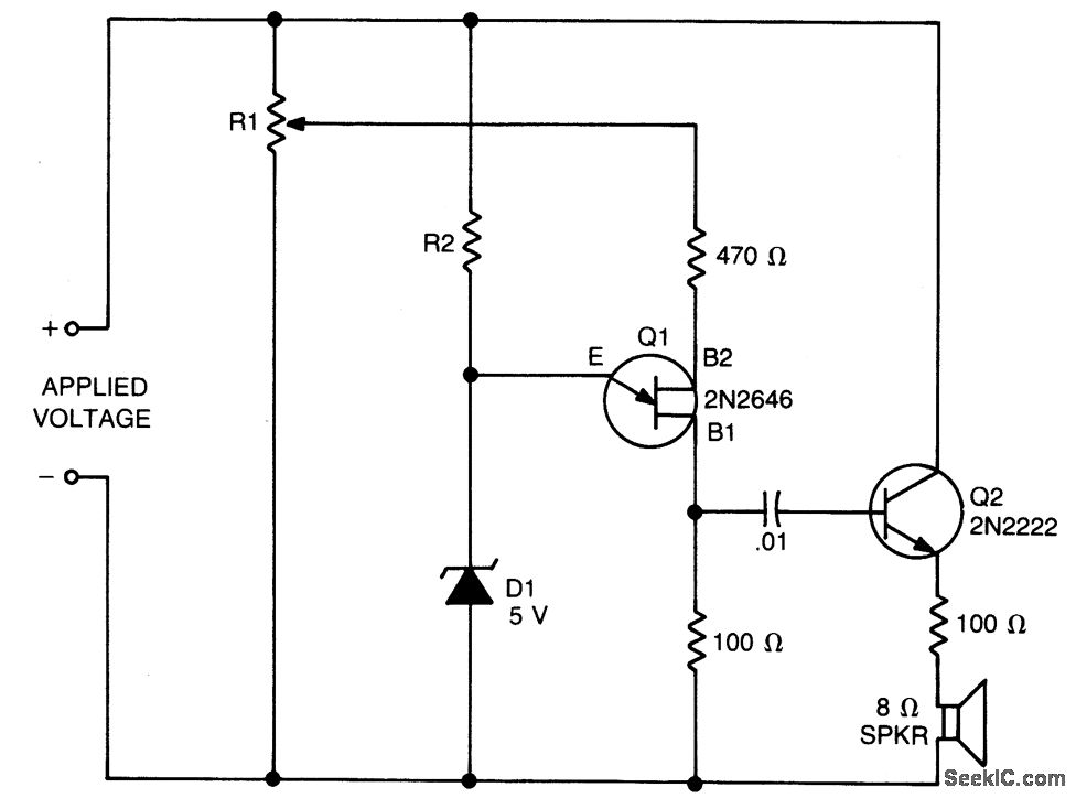
The values of R1, R2, and D1 are selected for the voltage applied. Using a 12-volt battery, R1= 10K, R2 = 5.6 K and Di is a 5-volt zener diode, or a string of forward-biased silicon rectifiers equaling about 5 volts. Transistor Q1 is a general-purpose UJT (Unijunction Transis-tor), and Q2 is any small-signal or switching NPN transistor. When detector is connected across the battery terminals, it draws little current and does not interfere with other devices powered by the battery. If voltage drops below the trip voltage selected with the R1 setting, the speaker beeps a waming. The fre-quency of the beeps is determined by the amount of undervoltage. If other voltages are being monitored, select R1 so that it draws only 1 mA or 2 mA. Zener diode D1 is about one-half of the desired trip voltage, and R2 is selected to bias it about 1 mA.
Reprinted Url Of This Article:
http://www.seekic.com/circuit_diagram/Measuring_and_Test_Circuit/LOW_VOLTAGE_DETECTOR.html
Print this Page | Comments | Reading(3)

Article Categories
power supply circuit
Amplifier Circuit
Basic Circuit
LED and Light Circuit
Sensor Circuit
Signal Processing
Electrical Equipment Circuit
Control Circuit
Remote Control Circuit
A/D-D/A Converter Circuit
Audio Circuit
Measuring and Test Circuit
Communication Circuit
Computer-Related Circuit
555 Circuit
Automotive Circuit
Repairing Circuit
Code: