Measuring and Test Circuit
STRIP_CHART_RECORDER_FROM_OLD_COMPUTER_PRINTER
Published:2009/7/16 5:29:00 Author:Jessie | From:SeekIC
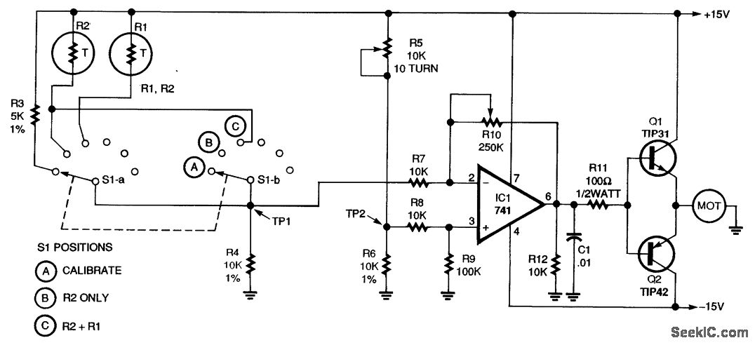
Converting an obsolete computer printer into a strip-chart recorder is both easy and inexpensive. The chart recorder works by comparing the voltage on a potentiometer to the voltage on a temperature-sensing thermistor. The potentiometer is mechanically connected to the printer carriage. A marking pen is also connected to the printer carriage. Any difference in the voltages on the potentiometer and the temperature sensor causes an op amp to attempt to bring the voltages back into balance. In the course of this, the print-head carriage is moved left or right, thereby causing a mark on the paper. A standard 741 op amp is used as a comparator. The comparator monitors the voltages at the junctions, marked TP1 and TP2. The op amp compares the voltages from the two networks at its inputs (pins 2 and 3). When the voltages are identical, the op amp's output (pin 6) is zero, so neither driver transistor (Q1 and Q2) turns on; therefore, the motor does not turn. But if thermistor R2's resistance changes because of a change in air temperature, a new voltage occurs at the op amp's inverting input (pin 2). For example, assume that R2 decreases.
The pin 2 voltage then increases, so the op amp's output swings negative, thereby biasing Q2 on. That in turn starts the motor, which moves the carriage left or right. Potentiometer R5 is also coupled to the carriage, so, as the carriage moves, R5's wiper moves, thereby varying the voltage on the noninverting input of IC1. When the op amp's input voltages become equal, the output goes to zero, both transistors turn off, and so does the motor. Now the circuit remains quiescent until the temperature changes again.
Reprinted Url Of This Article:
http://www.seekic.com/circuit_diagram/Measuring_and_Test_Circuit/STRIP_CHART_RECORDER_FROM_OLD_COMPUTER_PRINTER.html
Print this Page | Comments | Reading(3)

Article Categories
power supply circuit
Amplifier Circuit
Basic Circuit
LED and Light Circuit
Sensor Circuit
Signal Processing
Electrical Equipment Circuit
Control Circuit
Remote Control Circuit
A/D-D/A Converter Circuit
Audio Circuit
Measuring and Test Circuit
Communication Circuit
Computer-Related Circuit
555 Circuit
Automotive Circuit
Repairing Circuit
Code: