Measuring and Test Circuit
Single-chip TRMS Power Measurement System AD8362 Demodulation Circuit
Published:2011/5/9 22:52:00 Author:Sharon | Keyword: Single-chip, TRMS, Power Measurement System, Demodulation | From:SeekIC
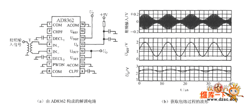
AD8362's UTGT side can constitute demodulation circuit. Take the envelope from the RF amplitude and restore it to the low and middle frequency signal before demodulation. The waveforms of the applied demodulation circuit and the process of obtaining envelope are shown in Figure (a), (b) below. It is assumed that the input signal is modulated 100kHz sine wave, and the carrier frequency is 100MHz. Link a voltage UT with an average of 1.25V, and 0.75V peak into the 14 feet, then the 12 feet's output voltage Uo is the 100kHz sine wave signal after its demodulation.
Reprinted Url Of This Article:
http://www.seekic.com/circuit_diagram/Measuring_and_Test_Circuit/Single_chip_TRMS_Power_Measurement_System_AD8362_Demodulation_Circuit.html
Print this Page | Comments | Reading(3)

Article Categories
power supply circuit
Amplifier Circuit
Basic Circuit
LED and Light Circuit
Sensor Circuit
Signal Processing
Electrical Equipment Circuit
Control Circuit
Remote Control Circuit
A/D-D/A Converter Circuit
Audio Circuit
Measuring and Test Circuit
Communication Circuit
Computer-Related Circuit
555 Circuit
Automotive Circuit
Repairing Circuit
Code: