power supply circuit
12_VDC_TO_117_VAC_AT_60_Hz_POWER_INVERTER
Published:2009/7/7 9:32:00 Author:May | From:SeekIC
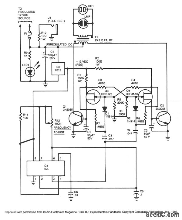
Capacitor C5 and potentiometer R12 determine the frequency of the output signal at pin 3 of IC1, the 555 oscillator. The output signal is differentiated by C3 and C4 before it's input to the base of power tran-sistors Q1 and Q2 via diodes Dl and D2, respectively. The signal from IC1 is adjusted to 120 Hz, because the f[ip-flop formed by transistors Q3 and Q4 divides the frequency by 2.When Q3 is on, the base of Q1 is connected via RI to the regulated 12-V supply. Then, when the flip-flop changes states, Q4 is turned on and the base of Q2 connected to the 12-V supply through R2. The 100 mA base current allows Q1 and Q2 to alternately conduct through their respective halves to the transform-er's secondary winding.To eliminate switching transients caused by the rapid switching of Q3 and Q4, capacitors C1 and C2 filter the inputs to the base of Q1 and Q2 respectively. Power for the unit comes from an automobile's 12-V system or from a storage battery. The power is regulated by IC2, a 7812 regulator. LED1, connected across the 12-V input, can be used to indicate whether power is being fed to the circuit. The neon pilot lamp, LMP1, shows a presence or absence of output power.
Reprinted Url Of This Article:
http://www.seekic.com/circuit_diagram/Power_Supply_Circuit/12_VDC_TO_117_VAC_AT_60_Hz_POWER_INVERTER.html
Print this Page | Comments | Reading(3)

Article Categories
power supply circuit
Amplifier Circuit
Basic Circuit
LED and Light Circuit
Sensor Circuit
Signal Processing
Electrical Equipment Circuit
Control Circuit
Remote Control Circuit
A/D-D/A Converter Circuit
Audio Circuit
Measuring and Test Circuit
Communication Circuit
Computer-Related Circuit
555 Circuit
Automotive Circuit
Repairing Circuit
Code: