power supply circuit
33_5_V_12_V_and__18_V_from_two_to_three_cells
Published:2009/7/24 23:19:00 Author:Jessie | From:SeekIC
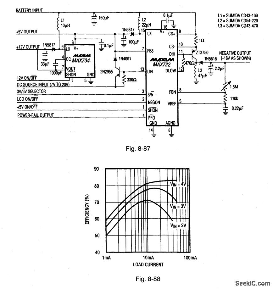
Figure 8-87 shows a MAX722 palmtop SMPS (surface-mount power supply), and a MAX734 regulator connected to provide a main 3.3-V/5-V output, a +12-V output for flash programming, and a -18-V output for LCD bias-all with a 1.8-V to 5.5-V input range. Quiescent current (when VIN = 3 V, and the 12-V line is off) is 350 μA. With a VIN of 2 V, the maximum load capability for the 5-V output is 200 mA, and the +12-V output, 40 mA. When VIN is increased to 2.5 V, the 5-V output provides 275 mA, and the +12-V output, 60 mA. Figure 8-88 shows the efficiency curves for the + 12-V output. If the main output is set at 3.3 V (pin 3 of the MAX722 high), connect the MAX734 V + pin to +12 V (instead of +5 V, as shown) to get the extra gate drive for the MAX734 MOSFET. MAXIM BATTERY MANAGEMENT CIRCUIT COLLECTION, 1994, P. 12.
Reprinted Url Of This Article:
http://www.seekic.com/circuit_diagram/Power_Supply_Circuit/33_5_V_12_V_and__18_V_from_two_to_three_cells.html
Print this Page | Comments | Reading(3)

Article Categories
power supply circuit
Amplifier Circuit
Basic Circuit
LED and Light Circuit
Sensor Circuit
Signal Processing
Electrical Equipment Circuit
Control Circuit
Remote Control Circuit
A/D-D/A Converter Circuit
Audio Circuit
Measuring and Test Circuit
Communication Circuit
Computer-Related Circuit
555 Circuit
Automotive Circuit
Repairing Circuit
Code: