power supply circuit
Emergency light using 6V battery cell automatic charger circuit 2
Published:2011/11/13 20:40:00 Author:May | Keyword: Emergency light, 6V, battery cell, automatic, charger | From:SeekIC
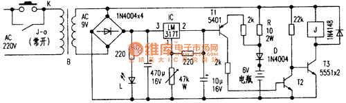
If it works forlong hours, its fever is serious, and it is easily to be destroyed. It is easily tolead to over-charge to cause the prematurely dry of electrolyte and shorting the battery life. For the shortcomings, the author changes it to auto-charger. After using six months, it works well. The circuit is shown in the above diagram.
Principle outline
It offers reference voltage for the base of T1. Relay J can achieve self-locking and automatic power off. When it is connected to the battery, K is pressed, power indicator L is lit, meanwhile J is energized and pulled in, K is self-locked by its contact J-0, and charging is starting. At this time, battery cell is under electrical, so T1 emitter voltage is less than (7.5V +0.65 V), T1 is cut off, T2 is also cut off, and this has no effect on the T3. When the battery voltage is charged to 7.5V, Tl emitter voltage is 7.5V +0.65 V, T1 is saturated and broken over, T2 is also broken over, T3 is cut off because its base voltage is dropped down, J is lost power and release, J-0 is cut, charging is stopped. Indicator light L goes out. It can charge to different voltage battery by adjusting W.
Reprinted Url Of This Article:
http://www.seekic.com/circuit_diagram/Power_Supply_Circuit/Emergency_light_using_6V_battery_cell_automatic_charger_circuit_2.html
Print this Page | Comments | Reading(3)

Article Categories
power supply circuit
Amplifier Circuit
Basic Circuit
LED and Light Circuit
Sensor Circuit
Signal Processing
Electrical Equipment Circuit
Control Circuit
Remote Control Circuit
A/D-D/A Converter Circuit
Audio Circuit
Measuring and Test Circuit
Communication Circuit
Computer-Related Circuit
555 Circuit
Automotive Circuit
Repairing Circuit
Code: