power supply circuit
Forward conversion type switching stabilized voltage supply isolating by photocoupler
Published:2011/11/22 1:28:00 Author:May | Keyword: Forward conversion, switching, stabilized voltage supply, photocoupler | From:SeekIC
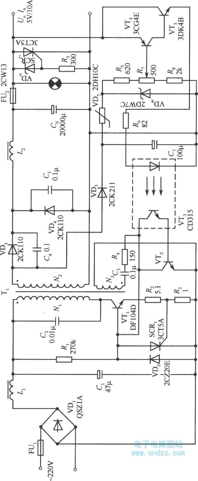
The diagram shows forward conversion switching stabilized voltage supply isolated by photo-coupler. VT1 is switching tube; VT2 and the photistor of photo-coupler VT3 make up compound variable resistance tube; VT4 and VT5 make up compound error amplifier. N2 is the secondary winding of high transformer T for DC outputting and sampling. N3 is self-oscillation positive feedback coil. In this circuit, DC voltage output end connects with sampling circuit of error amplifier, but thesignal output by amplifier is not connecting to the circuit, thereby it achieves the electrical isolation of sampling circuit for error amplifier and switching tube.
When output voltage increases, emitter current of compound error amplifier VT4 and VT5 increases. This current passes the LED in photo-coupler to make its illumination become larger.
Reprinted Url Of This Article:
http://www.seekic.com/circuit_diagram/Power_Supply_Circuit/Forward_conversion_type_switching_stabilized_voltage_supply_isolating_by_photocoupler.html
Print this Page | Comments | Reading(3)

Article Categories
power supply circuit
Amplifier Circuit
Basic Circuit
LED and Light Circuit
Sensor Circuit
Signal Processing
Electrical Equipment Circuit
Control Circuit
Remote Control Circuit
A/D-D/A Converter Circuit
Audio Circuit
Measuring and Test Circuit
Communication Circuit
Computer-Related Circuit
555 Circuit
Automotive Circuit
Repairing Circuit
Code: