power supply circuit
Isolated Voltage Sensors for Monitoring Power Supply
Published:2013/3/18 21:13:00 Author:Ecco | Keyword: Isolated Voltage Sensors, Monitoring Power Supply | From:SeekIC
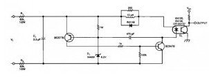
This is simple VCO ( voltage controlled oscillator) circuit , connected to your current instrumentation by an optoisolator, means that you can measure high voltages of your instrumentation more secure. The component values suit a 0 to 600 V input range (power dissipation in R1 and R2 set a limit on the input-voltage range). The circuit’s linearity is not an issue, because you can linearize its output in software.
The input voltage (VI), charges capacitor C1 until zener diode D1 conducts. Then, the zener diode triggers an “avalanche” circuit that discharges C1 into optocoupler Q1. After Cl discharges, the charging cycle repeats. C1 also averages the sensed-voltage level, which thereby provides noise immunity.
Reprinted Url Of This Article:
http://www.seekic.com/circuit_diagram/Power_Supply_Circuit/Isolated_Voltage_Sensors_for_Monitoring_Power_Supply.html
Print this Page | Comments | Reading(3)

Article Categories
power supply circuit
Amplifier Circuit
Basic Circuit
LED and Light Circuit
Sensor Circuit
Signal Processing
Electrical Equipment Circuit
Control Circuit
Remote Control Circuit
A/D-D/A Converter Circuit
Audio Circuit
Measuring and Test Circuit
Communication Circuit
Computer-Related Circuit
555 Circuit
Automotive Circuit
Repairing Circuit
Code: