power supply circuit
MICROPOWER_VOLTAGE_TO_FREQUENCY_CONVERTER
Published:2009/7/14 22:43:00 Author:Jessie | From:SeekIC
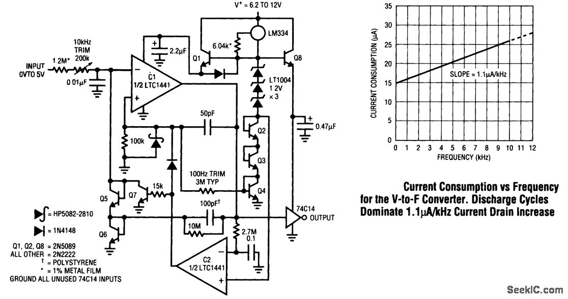
This voltage-to-frequency converter takes full advantage of the LTC1441's low power consumption under dynamic conditions. A 0- to 5-V input produces a 0- to 10-kHz output with 0.02 percent linearity, 60 ppm/°C drift, and 40 ppm/V supply rejection. Maximum current consumption is only 26μA, 100 times lower than that of currently available circuits. C1 switches a charge pump, composed of Q5, Q6, and the 100-pF capacitor, to maintain its negative input at 0 V. The LT1004s and associated components form a temperature- compensated reference for the charge pump. The 100-pF capacitor charges to a fixed voltage; hence, the repetition rate is the circuit's only degree of freedom to maintain feedback. Comparator C1 pumps uniform packets of charge to its negative input at a repetition rate precisely proportional to the input voltage-derived current.This action ensures that circuit output frequency is strictly and solely determined by the input volt-age. Start-up or input overdrive can cause the circuit's ac-coupled feedback to latch. If this occurs, C1's output goes low; C2, detecting this via the 2.7-MΩ/0.1-μF lag, goes high. This lifts C1's positive input and grounds the negative input with Q7, initiating normal circuit action.
Reprinted Url Of This Article:
http://www.seekic.com/circuit_diagram/Power_Supply_Circuit/MICROPOWER_VOLTAGE_TO_FREQUENCY_CONVERTER.html
Print this Page | Comments | Reading(3)

Article Categories
power supply circuit
Amplifier Circuit
Basic Circuit
LED and Light Circuit
Sensor Circuit
Signal Processing
Electrical Equipment Circuit
Control Circuit
Remote Control Circuit
A/D-D/A Converter Circuit
Audio Circuit
Measuring and Test Circuit
Communication Circuit
Computer-Related Circuit
555 Circuit
Automotive Circuit
Repairing Circuit
Code: