
Power-Supply Circuits-DC to DC
Index 2
Regulator DC-DC Circuit and Pin of Power Supply Monitor and Step-up Regulator
Published:2011/9/7 3:33:00 Author:Zoey | Keyword: Regulator, DC-DC Circuit, Pin, Step-up Regulator
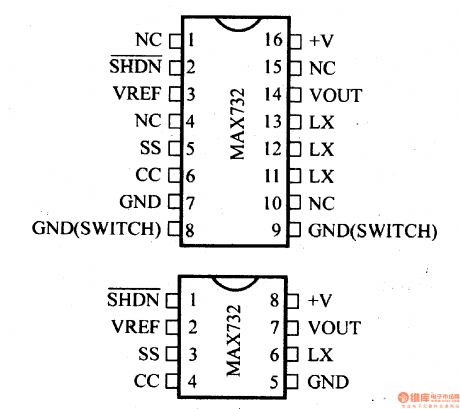
MAX732/733 refers to the DC-DC current PWM step-up regulator. As to MAX732, output voltage is +12V, maximum output current is 200mA, output voltage range is +4.0~+9.3V. And as to MAX733, the relevant values are +15V, 125mA and 4.0V~11.V respectively. Typical value of full load efficiency is 85%~92%, of empty load current is 1.7mA. Oscillation frequency is 170 kHz. The regulator has protection circuits for periodic current-proof, overcurrent-proof, undervoltage-proof and programmable soft-start. (View)
View full Circuit Diagram | Comments | Reading(1273)
Regulator DC-DC Circuit and Pin of Power Supply Monitor and Power Supply System
Published:2011/9/7 3:36:00 Author:Zoey | Keyword: Regulator, DC-DC Circuit, Pin, Power Supply System
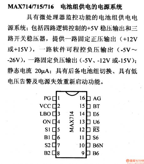
MAX714/715/716 refers to the power supply system powered by cell piles. It has a micro-processor for detection. This system consists of a four-loop logic-controlled +5-V regulator and a three-loop switched regulator, a fixed positive output single-loop(+12V or +15V), a software-controlled negative output single-loop and a fixed negative single-loop. Its static current is 20A. This system has a spare cell piles switch, a low voltage warner and it can restart if the cell lapses. (View)
View full Circuit Diagram | Comments | Reading(797)
Step-down converting power circuit composed Of MC34063
Published:2011/5/5 20:03:00 Author:May | Keyword: Step-down, converting power
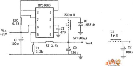
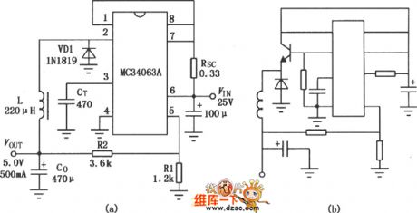
Step-down Vary Power Circuit Composed ofMC34063 is shown in the diagram. MC34063 is a type of switching modehighly active DC/DC Changed circuits. Its internalincludes reference voltage source withthe function of temperature compensation, comparator, duty ration controllable oscillator with limited current circuit, driver and heavy current output switch tube. The +25V/+5V step-down vary power composed of it is shown in the picture, the features are: (VIN=25V when IO=500mA) line regulation is 12mV±0.12%; load regulation is 3mV±0.03%; ripple voltage is 120mV. If one-level filter (shown in figure) output ripple reduced to 40mV; conversion efficiency is 82%; short-circuit limiting current is 1.1A.
(View)
View full Circuit Diagram | Comments | Reading(6425)
Phase Detection and Double Direction Counting Circuit of EPC-755A
Published:2011/7/13 7:08:00 Author:Michel | Keyword: Phase Detection, Double DirectionCounting, Circuit

EPC-755A photoelectric encoder has good performance and has good anti-interference in angle and displacement measuring.EPC-755A photoelectric encode also owns stable and reliable output pulse signal, and the pulse signal can be obtained after the count is measured in digital signal.On the steering wheel rotation angle measurement EPC-755 A photoelectric encoder is chosen as sensor when we develop a driving simulator in the car.Its output circuit chooses open collector and output resolution selects 360 pieces of pulses/circles,which can be clockwise and counterclockwise,considering the steering wheel rotation is bidirectional,and it can be counted after detecting the output signal of the encoder. (View)
View full Circuit Diagram | Comments | Reading(1105)
Digital controlled adjustable integrated regulated power supply circuit diagram
Published:2011/5/10 22:18:00 Author:Rebekka | Keyword: Digital controlled, adjustable integrated regulated power supply
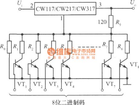
Here is the diagram of digital controlled adjustable integrated regulated power supply circuit composed of CW117, CW217 and CW317.
The figure shows the digital control adjustable integrated regulated power supply. Digital control input is 8-bit binary code. Reasonable choice for the resistance resistance R0 ~ R8 can get the CNC adjustable integrated regulated power supply that its output voltage is 2.5 ~ 120V and stepping value is 0.5V. The precision requirement of resistance R0 ~ R8 is high. The requirement of the high binary code resistance is highest. Such as when the accuracy of R0 and R8 is ± 0.1%, the output precision of 120V high-voltage is about 0.5V. When the 8-bit binary code is 00000000 , the transistor VT1 ~ VT8 all stop, the output voltage is maximum. When the 8-bit binary code shows 11111111 , the transistor VTl ~ VT8 are all turned on, R0 ~ R8 9 resistors in parallel is equivalent to the resistance R2 of the standard circuit, then the output voltage is the lowest. Adjust the output voltage to make the input and output voltage of the integrated regulator is less than the allowed value(40V). (View)
View full Circuit Diagram | Comments | Reading(1662)
MC3406A buck-boost DC-DC convertor integrated circuit diagram
Published:2011/5/5 7:32:00 Author:Nicole | Keyword: Integrated convertor
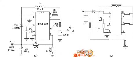
MC3406A is a new monolithic buck-boost DC-DC converter integrated circuit, the input voltage is 3 ~ 40V, output voltage isadjustable, the output switch current can up to l. 5A, and it hasa temperature compensated voltage reference, it has the function of current limit. The IC is equipped with only a few external components, then it can form boost, buck, anti-transition DC-DC converter, it can be widely used in various portable instruments, meters and so on.
MC3406A used as boost DC-DC convertor circuit:
MC3406A used as buck DC-DC convertor circuit:
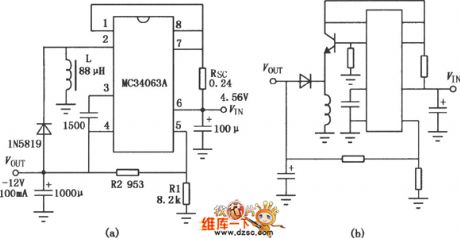
MC3406A used as anti-transition DC-DC convertor circuit:
(View)
View full Circuit Diagram | Comments | Reading(3765)
Output boost adjustable power composed Of MAX761 circuit diagram
Published:2011/3/30 5:04:00 Author:may | Keyword: Output boost adjustable, power
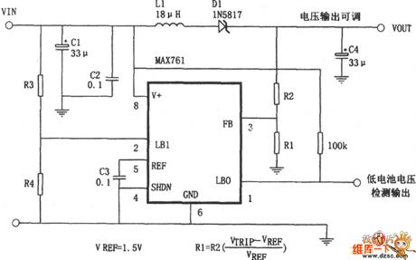
The diagram is output boost adjustable transform power, itconsists of highly active, low power consumption Step Up DC convertor MAX761 and some peripheral cells. The output voltage depends on the specific value of R2 and R1, it can calculate according to the formula V0=(1+R2/R1)×VREF, VREF=1.5V.
(View)
View full Circuit Diagram | Comments | Reading(741)
Polarity reversal boost power supply circuit diagram composed of LT1172
Published:2011/4/2 4:38:00 Author:Nicole | Keyword: boost power supply
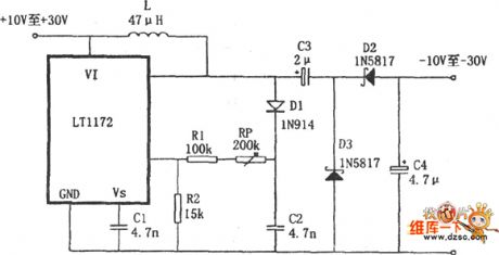
As shown, this is a polarity reversal boost power supply which is composed of boost switching regulator LT1172. The output voltage is -10 ~-30V, output current is 25mA, conversion efficiency is 80%. It uses the LT1172 to boost, and connect a charge pump which composed of C1, C2, D2, D3 on the output termination of LT1172, then to complete the output voltage polarity reversal.
(View)
View full Circuit Diagram | Comments | Reading(1813)
Micro-power polarity reversal circuit diagram composed of MAX1721
Published:2011/4/2 4:34:00 Author:Nicole | Keyword: Micro-power polarity reversal
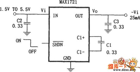
As shown, micro-power polarity reversal composed of miniature (SOT23 package) inverting charge pump IC MAX1721. This circuit just need take a 0.33μF little capacity, small size capacitor on the outside of MAX1721, then the polarity reversal can be completed, that is the output voltage Vo =- Vi.
(View)
View full Circuit Diagram | Comments | Reading(817)
High input voltage DC / DC converter circuit diagram
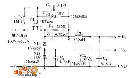
Published:2011/4/1 3:35:00 Author:Nicole | Keyword: DC / DC converter, high input voltage
View full Circuit Diagram | Comments | Reading(1969)
Highly-efficient step-up power supply circuit diagram composed of MAX632
Published:2011/3/23 3:01:00 Author:Nicole | Keyword: step-up power supply
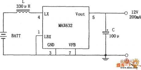
As shown, this is the highly-efficient step-up power supply circuit diagram composed of MAX632. MAX6a is a high efficiency, few external components, low-power integrated switching regulator. Since switching power transistor and freewheeling diode has been integrated inside the chip, the MAX632 only need a energy storage inductor and a filter capacitor externally, it can easily form a Boost power circuit. The input voltage is range from +1.5 V to +12 V.
(View)
View full Circuit Diagram | Comments | Reading(1779)
Car audio power supply DC-DC converter circuit diagram
Published:2011/3/21 1:42:00 Author:Rebrecca | Keyword: Car audio, power supply, DC-DC converter
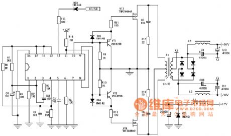
The car audio power supply DC-DC converter circuit is shown as below.
(View)
View full Circuit Diagram | Comments | Reading(11716)
| Pages:2/2 12 |
Circuit Categories
power supply circuit
Amplifier Circuit
Basic Circuit
LED and Light Circuit
Sensor Circuit
Signal Processing
Electrical Equipment Circuit
Control Circuit
Remote Control Circuit
A/D-D/A Converter Circuit
Audio Circuit
Measuring and Test Circuit
Communication Circuit
Computer-Related Circuit
555 Circuit
Automotive Circuit
Repairing Circuit