power supply circuit
Practical circuit of push-pull converter type switching regulated power supply
Published:2011/11/21 21:20:00 Author:May | Keyword: push-pull converter type, switching regulated power supply | From:SeekIC
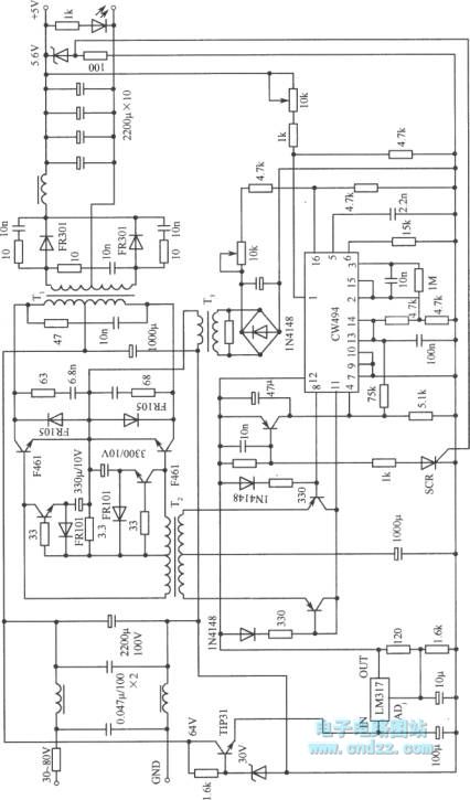
The diagram shows a practical circuit of push-pull converter type switching regulated power supply. CW494 is double-ended converter modulator integrated circuit which includes error amplifier, voltage reference, clock oscillator, pulse width modulator and other circuits. Transformer T1 is high-frequency transformer which can transfer energy to the load. T2 is incentive promotion transformer. It can transmit two strings of pulse modulator outputted by CW494 pulse modulator to drive and switching tube base of push pull circuit after it enlarged through incentives promote transistor. Winding transformer T3 is the sampling pulse of AC voltage on the transformer and rectified through by the sample sent to the pulse modulation circuit resistance CW494 16 feet, as the error amplifier inverting input.
The selection of power switching power transistor is fast series F461. In the place where the voltage is feedback, input and output are directly connected. If the input and output need to be isolated, the optocoupler can be used.
Reprinted Url Of This Article:
http://www.seekic.com/circuit_diagram/Power_Supply_Circuit/Practical_circuit_of_push_pull_converter_type_switching_regulated_power_supply.html
Print this Page | Comments | Reading(3)

Article Categories
power supply circuit
Amplifier Circuit
Basic Circuit
LED and Light Circuit
Sensor Circuit
Signal Processing
Electrical Equipment Circuit
Control Circuit
Remote Control Circuit
A/D-D/A Converter Circuit
Audio Circuit
Measuring and Test Circuit
Communication Circuit
Computer-Related Circuit
555 Circuit
Automotive Circuit
Repairing Circuit
Code: