power supply circuit
Pulse type automatic charger (1)
Published:2011/7/14 21:53:00 Author:TaoXi | Keyword: Pulse type, automatic charger | From:SeekIC
Operating principle:
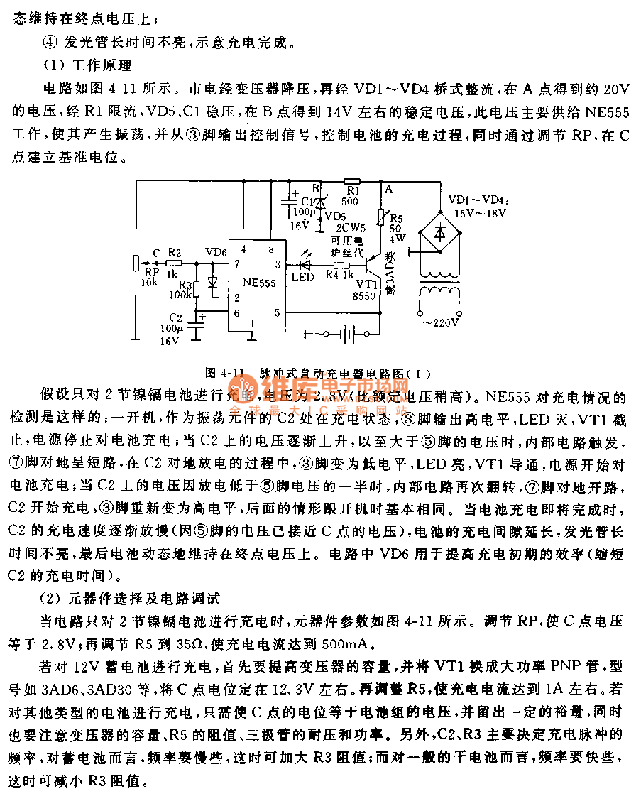
The circuit is as shown in figure 4-11, the city electricity is reduced by the transformer and is bridge-type rectified by VD1-VD4, so point A gets the 20V voltage, this voltage is limited by R1, stabilized by VD5 and C1, so point B gets the 14V stabe voltage, this voltage is supplied to NE555, so the NE555 produces the oscillation and outputs the control signal from pin-3 to control the charging process, by adjusting RP, we can establish the reference potential at C point.
IF you want to charge the 12V storage battery, you need to improve the transformer capacity, and the VT1 need to use the high power PNP transistor such as the 3AD6, 3AD30. The electric potential of point C is about 12.3V.
Reprinted Url Of This Article:
http://www.seekic.com/circuit_diagram/Power_Supply_Circuit/Pulse_type_automatic_charger_1.html
Print this Page | Comments | Reading(3)

Article Categories
power supply circuit
Amplifier Circuit
Basic Circuit
LED and Light Circuit
Sensor Circuit
Signal Processing
Electrical Equipment Circuit
Control Circuit
Remote Control Circuit
A/D-D/A Converter Circuit
Audio Circuit
Measuring and Test Circuit
Communication Circuit
Computer-Related Circuit
555 Circuit
Automotive Circuit
Repairing Circuit
Code: