power supply circuit
Pulse type automatic charger circuit (3)
Published:2011/7/14 21:17:00 Author:TaoXi | Keyword: Pulse type, automatic, charger circuit | From:SeekIC
Operating principle:
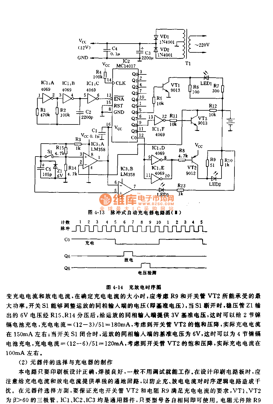
The circuit principle diagram of this charger is as shown in figure 4-13. The power transformer T1 changes the 220V AC into the 9V AC, and this 9V AC is rectified by VD1 and VD2, then it is filted by C3 to supply the 12V DC voltage to the charger, the capacitance C4 can be used in filtering. The oscillator is composed of the IC1:A, IC2:B and the external components, IC1:C is the buffer stage of the oscillator, the output of IC1:C supplies the clock pulse for the counter IC2. IC2 is the decimal counter, it can be used to control the charging time and discharging time of the charger, and it counts the lower edge of the clock pulse. The charging and discharging timing sequence is as shown in figure 4-14.
Reprinted Url Of This Article:
http://www.seekic.com/circuit_diagram/Power_Supply_Circuit/Pulse_type_automatic_charger_circuit_3.html
Print this Page | Comments | Reading(3)

Article Categories
power supply circuit
Amplifier Circuit
Basic Circuit
LED and Light Circuit
Sensor Circuit
Signal Processing
Electrical Equipment Circuit
Control Circuit
Remote Control Circuit
A/D-D/A Converter Circuit
Audio Circuit
Measuring and Test Circuit
Communication Circuit
Computer-Related Circuit
555 Circuit
Automotive Circuit
Repairing Circuit
Code: