power supply circuit
Push pull type switching regulated power supply principle diagram
Published:2011/11/21 21:15:00 Author:May | Keyword: Push pull type, switching regulated power supply | From:SeekIC
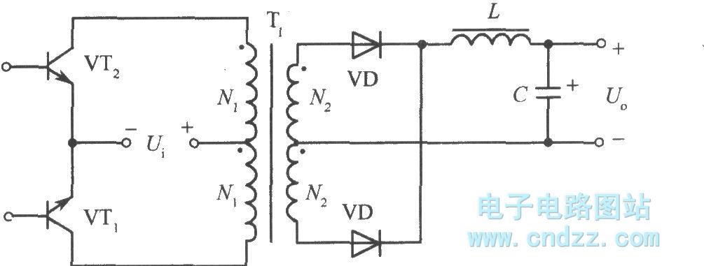
Push-pull converter circuit belongs to double-ended type conversion circuit. Its high-frequency transformer works atboth sides of the hysteresis loop. The typical circuit is shown as the chart. Switching transistors VT1, VT2 are alternately turned on and off after inspiring by base driving circuit, the input DC voltage Ui is converted into high frequency square wave AC voltage. When VTl is turned on, Ui is added to the primary winding N1 of the transformer T1 by VT1. When the base incentive disappears, VTl, VT2 tubes are closed. The collector voltage is input voltage Ui. Next half cycle, VT2 is turned on, VTl is ended, VT1 can add two times input voltage, after the two tubes cut off, and the next cycle is started again. The main disadvantage of push-pull circuit isthat switching transistor voltage should reach 2 times of input power. To take 220 ± 10% V grid voltage for an example of peak voltage, the maximum steady state cutoff voltage is 680V.
Reprinted Url Of This Article:
http://www.seekic.com/circuit_diagram/Power_Supply_Circuit/Push_pull_type_switching_regulated_power_supply_principle_diagram.html
Print this Page | Comments | Reading(3)

Article Categories
power supply circuit
Amplifier Circuit
Basic Circuit
LED and Light Circuit
Sensor Circuit
Signal Processing
Electrical Equipment Circuit
Control Circuit
Remote Control Circuit
A/D-D/A Converter Circuit
Audio Circuit
Measuring and Test Circuit
Communication Circuit
Computer-Related Circuit
555 Circuit
Automotive Circuit
Repairing Circuit
Code: