power supply circuit
Separately excited switching regulated power supply circuit 3
Published:2011/4/25 21:17:00 Author:May | Keyword: Separately excited, switching, regulated power supply | From:SeekIC

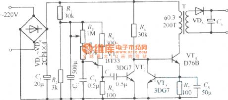
The diagram is separately excited switching regulated power supply circuit which using self-excited multivibrator as pulse generator. In the diagram, VTl is switching tube; VT2, VT3 is pushing tube; VT4 is emitter follower. Separately excited oscillation circuit is self-excited multivibrator consists of VT5, VT6, C2, C3, R3, R4, etc. VT7, VT8 forms emitter-coupled differential amplifier and it uses as error amplifier. Sampling circuit consists of resistor R7, R8 and potentiometer R9 in series. Reference voltage source circuit is composed of diode VD4 and R5. Diode VDl, VD2 is used to prevent the push tube VT2, VT3 emitter breakdown by reverse voltage. VD3 is freewheeling diode; L is energy storage inductor.
Switching regulator's turn-on and cut-off is overturned by multivibrator and controlled by emitter follower VT4.The time of multivibrator’s reversal is determined by error amplifier. That is to say, the reversal time of VT5 from cut off to turned off is determined by the charging current of V8 to C3. If the current of VT is larger, the cut off time of VT5 is longer.
Reprinted Url Of This Article:
http://www.seekic.com/circuit_diagram/Power_Supply_Circuit/Separately_excited_switching_regulated_power_supply_circuit_3.html
Print this Page | Comments | Reading(3)

Article Categories
power supply circuit
Amplifier Circuit
Basic Circuit
LED and Light Circuit
Sensor Circuit
Signal Processing
Electrical Equipment Circuit
Control Circuit
Remote Control Circuit
A/D-D/A Converter Circuit
Audio Circuit
Measuring and Test Circuit
Communication Circuit
Computer-Related Circuit
555 Circuit
Automotive Circuit
Repairing Circuit
Code: