Position: Home > Circuit Diagram > power supply circuit > Synchronous step-down voltage stabilizer circuit
power supply circuit
Synchronous step-down voltage stabilizer circuit
Published:2011/6/19 9:14:00 Author:TaoXi | Keyword: Synchronous, step-down, voltage, stabilizer | From:SeekIC
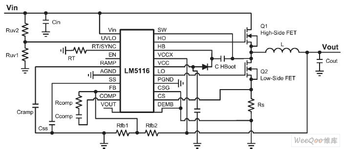
The basic structure of the DC-DC buck regulator circuit is as shown in the figure, this device uses the LM5116 as the pulse width modulator (PWM) switch controller. The critical current path is from the VIN to the output port through the high-side FET; another choose is from the grounding port to the output port through the Rs and the low-side FET. The power loss which is produced along this path is the main loss.
Reprinted Url Of This Article:
http://www.seekic.com/circuit_diagram/Power_Supply_Circuit/Synchronous_step_down_voltage_stabilizer_circuit.html
Print this Page | Comments | Reading(3)

Article Categories
power supply circuit
Amplifier Circuit
Basic Circuit
LED and Light Circuit
Sensor Circuit
Signal Processing
Electrical Equipment Circuit
Control Circuit
Remote Control Circuit
A/D-D/A Converter Circuit
Audio Circuit
Measuring and Test Circuit
Communication Circuit
Computer-Related Circuit
555 Circuit
Automotive Circuit
Repairing Circuit
Code: