Remote Control Circuit
The infrared temperature control circuit composed of heat releasing electric sensors
Published:2011/7/20 1:18:00 Author:Borg | Keyword: infrared temperature control circuit, heat releasing electric sensors | From:SeekIC
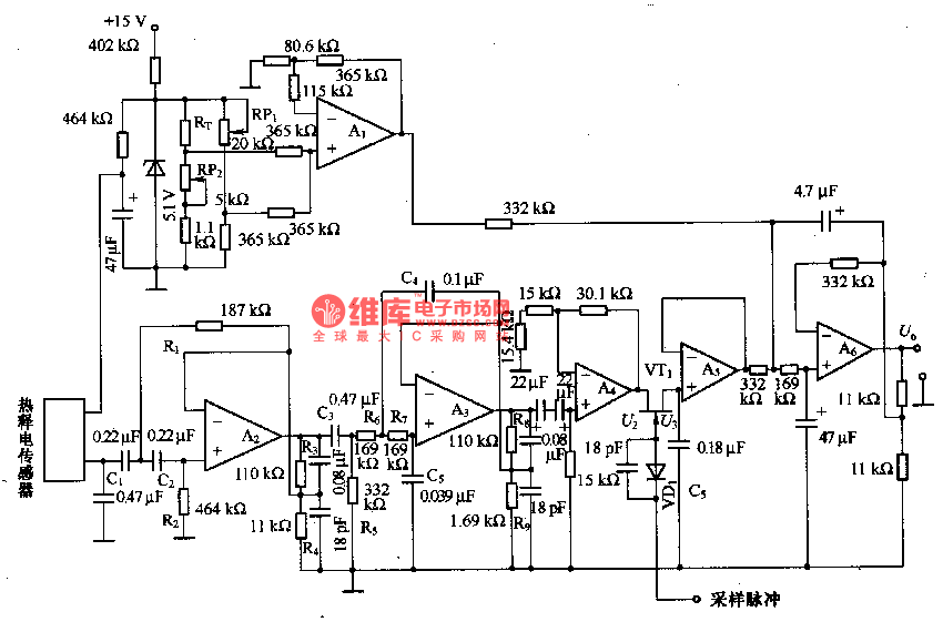
The temperature compensation circuit consists of RT and A1. A6 composes the addition circuit, A6 adds up the outputs of the temperature compensation circuit and the synchronous rectifier circuit, whose output is the corresponding voltage of the object temperature under test. In figure (b) is the amplifier part, detection part, timing part and relay drive part and so on of the circuit. The power supply of the circuit is DC 6-8V, the working current is 70mA, the standby current is 2mA, the maximum range of the sensor is 5m, the time is about 5-22S.
Reprinted Url Of This Article:
http://www.seekic.com/circuit_diagram/Remote_Control_Circuit/The_infrared_temperature_control_circuit_composed_of_heat_releasing_electric_sensors.html
Print this Page | Comments | Reading(3)

Article Categories
power supply circuit
Amplifier Circuit
Basic Circuit
LED and Light Circuit
Sensor Circuit
Signal Processing
Electrical Equipment Circuit
Control Circuit
Remote Control Circuit
A/D-D/A Converter Circuit
Audio Circuit
Measuring and Test Circuit
Communication Circuit
Computer-Related Circuit
555 Circuit
Automotive Circuit
Repairing Circuit
Code: