Signal Processing
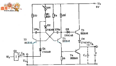
5MHz clock signal generater circuit
Published:2011/4/24 1:10:00 Author:May | Keyword: clock signal generater | From:SeekIC

The transistor T1, T2 form a multiple harmonic oscillator, and connect to 500Ω adjustable resistance in series with fixed resistance R1 can adjust frequency. Transistor T3 and T4 compose output level, output current IQ is larger than 48mA when the low level UQL=0.4V, and 20mA when the high level UQH is 2.9V.
Reprinted Url Of This Article:
http://www.seekic.com/circuit_diagram/Signal_Processing/5MHz_clock_signal_generater_circuit.html
Print this Page | Comments | Reading(3)

Article Categories
power supply circuit
Amplifier Circuit
Basic Circuit
LED and Light Circuit
Sensor Circuit
Signal Processing
Electrical Equipment Circuit
Control Circuit
Remote Control Circuit
A/D-D/A Converter Circuit
Audio Circuit
Measuring and Test Circuit
Communication Circuit
Computer-Related Circuit
555 Circuit
Automotive Circuit
Repairing Circuit
Code: