Signal Processing
Audio frequency oscillator circuit diagram with adjustable frequency composed of μA741
Published:2011/8/10 4:26:00 Author:nelly | Keyword: Audio frequency oscillator, adjustable frequency | From:SeekIC
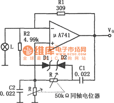
As shown in the figure, it is the audio frequency oscillator circuit with adjustable frequency. Beside using bulb control gain, the circuit also has the automatic gain control circuit which is composed of zener diodes D1, D2 and resistance R2. With the frequency's dropping, the output amplitude will increase. When the output amplitude increases to the preset value, then the zener diode turns on. So the amplifier's gain decreases, and it can avoid the amplifier saturating. R2 is used to decrease the amplitude limit of zener diode, then it can avoid excessive distortion.
Reprinted Url Of This Article:
http://www.seekic.com/circuit_diagram/Signal_Processing/Audio_frequency_oscillator_circuit_diagram_with_adjustable_frequency_composed_of_μA741.html
Print this Page | Comments | Reading(3)

Article Categories
power supply circuit
Amplifier Circuit
Basic Circuit
LED and Light Circuit
Sensor Circuit
Signal Processing
Electrical Equipment Circuit
Control Circuit
Remote Control Circuit
A/D-D/A Converter Circuit
Audio Circuit
Measuring and Test Circuit
Communication Circuit
Computer-Related Circuit
555 Circuit
Automotive Circuit
Repairing Circuit
Code: