Signal Processing
ONE_FILTER_THREE_PHASE_SINE_WAVE_GENERATOR
Published:2009/7/13 22:57:00 Author:May | From:SeekIC


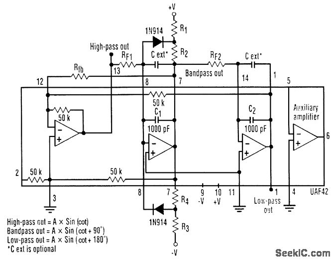
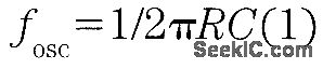


It is possible to build a three-phase sine-wave oscillator using just one UAF42 state variable filter along with some resistors and diodes. Three output nodes are available: high-pass out, bandpass out, and low-pass out. The signals at the bandpass and low-pass out nodes are 90°and 180° out of phase, respectively, with those at the high-pass out node. An on-board auxiliary op amp is available for use as a buffer or gain stage. The frequency of oscillation is set with resistors RF1 and RF2 using the simple equation:The maximumfosc obtainable using the UAF42 state-variable filter is 100 kHz. However, distortion becomes a factor for frequencies above 10 kHz. Resistance R1, R2, R3, and R4, should be selected using the following equation to set the desired signal amplitude:Resistor Rfb provides a positive feedback path from the bandpass out node to the summing-amplifier input. This provides the necessary startup required to begin oscillation. Suggested values are as follows:To design a 1-kHz,1.2-V peak oscillator,use Eq 1 to calculate RF1 and RF2∶Use Eq.2 to determine values for the signal magnitude-setting resistances R1/R2 and R3/R4:Setting R1 and R3 equal to 15.4 kΩ and R2 and R4 equal to 1 kΩ would provide the proper resistor ratios These resistors act as loads to the internal op amp
Reprinted Url Of This Article:
http://www.seekic.com/circuit_diagram/Signal_Processing/ONE_FILTER_THREE_PHASE_SINE_WAVE_GENERATOR.html
Print this Page | Comments | Reading(3)

Article Categories
power supply circuit
Amplifier Circuit
Basic Circuit
LED and Light Circuit
Sensor Circuit
Signal Processing
Electrical Equipment Circuit
Control Circuit
Remote Control Circuit
A/D-D/A Converter Circuit
Audio Circuit
Measuring and Test Circuit
Communication Circuit
Computer-Related Circuit
555 Circuit
Automotive Circuit
Repairing Circuit
Code: