Oscillator Circuit
1024KHz temperature compensation crystal oscillator circuit diagram
Published:2011/8/9 19:59:00 Author:Sophia | Keyword: 1024KHz temperature compensation, crystal oscillator | From:SeekIC
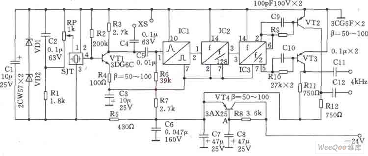
This circuit SJT is 1024kHz temperature compensation crystal oscillator. Circuit theoryis asshown. Because output signal level of the circuit is low, the buffer of follow-up transistor VTl is amplified. VTl base bias resistor R2, the load resistor R3, the emitter resistor R4 are the negative feedback resistors for stablizing VTl DC operating point. Zener diode VDl, VD2, capacitor Cl form stabilivolt and filter circuit to reduce the influency of the supply voltage fluctuations on the frequency of the crystal SJT. Resistors Rl and potentiometer RP TCXO provide bias voltage. regulation of RP can fine-tune the oscillator to reach precise frequency.
Reprinted Url Of This Article:
http://www.seekic.com/circuit_diagram/Signal_Processing/Oscillator_Circuit/1024KHz_temperature_compensation_crystal_oscillator_circuit_diagram.html
Print this Page | Comments | Reading(3)

Article Categories
power supply circuit
Amplifier Circuit
Basic Circuit
LED and Light Circuit
Sensor Circuit
Signal Processing
Electrical Equipment Circuit
Control Circuit
Remote Control Circuit
A/D-D/A Converter Circuit
Audio Circuit
Measuring and Test Circuit
Communication Circuit
Computer-Related Circuit
555 Circuit
Automotive Circuit
Repairing Circuit
Code: