Oscillator Circuit
Low frequency oscillator (flashing shine circuit) circuit 1 made by 555 time-base circuit
Published:2011/5/12 2:03:00 Author:Ecco | Keyword: Low frequency, oscillator, flashing, shine , 555, time-base circuit | From:SeekIC
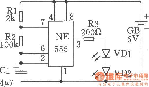
The chart shows a flashing shine circuit, and when the circuit works, twolight-emitting diodes will shine simultaneously. The working principle of the circuit is similar to 555 audio oscillator, the difference is that the capacity of capacitor Clis increased to 4.7μF. Therefore, the circuit's oscillation frequency is very low, the changing rate of potential on pin 3 of NE555 is low. When the output of pin 3is inhigh level, the light-emitting diode VDl, VD2 are lit at the same time. When the output of pin 3is inlow level, the light-emitting diode VDl, VD2 turns off.In the circuit, when the resistance of R3 is higher, the brightnessis smaller; or resistance of R3 is lower, the brightnessis greater. Note:theresistance of R3 should not be too small, otherwise the current flowing through the light-emitting diodes is too high, the power consumption is higher,it will have negative impact on thelight-emitting diode, or even it is burned. Typically, the current flowing through the LED can be controlled between 10 ~ 20mA.
Reprinted Url Of This Article:
http://www.seekic.com/circuit_diagram/Signal_Processing/Oscillator_Circuit/Low_frequency_oscillator_flashing_shine_circuit_circuit_1_made_by_555_time_base_circuit.html
Print this Page | Comments | Reading(3)

Article Categories
power supply circuit
Amplifier Circuit
Basic Circuit
LED and Light Circuit
Sensor Circuit
Signal Processing
Electrical Equipment Circuit
Control Circuit
Remote Control Circuit
A/D-D/A Converter Circuit
Audio Circuit
Measuring and Test Circuit
Communication Circuit
Computer-Related Circuit
555 Circuit
Automotive Circuit
Repairing Circuit
Code: