Oscillator Circuit
Low frequency oscillator (flashing shine circuit) circuit 2 made by 555 time-base circuit
Published:2011/5/12 2:01:00 Author:Ecco | Keyword: Low frequency , oscillator, flashing, shine , 555 , time-base circuit | From:SeekIC
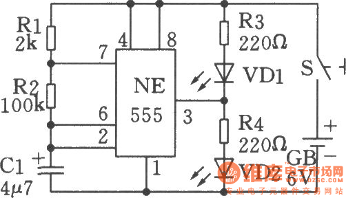
The chart shows the flashing shine circuit based on 555 circuit,and when the circuit works, two light-emitting diodes will shine
alternately. The working principle: The NE555 time-base circuit and Rl、R2、Cl form a low frequency oscillator. When the circuit starts oscillation, the level of pin 3 in theNE555 time-base circuitis variable. When pin 3 is in high level, VD1 loses power and doesn't emit light, VD2 gets power and emits light; when pin 3 is inlow level, VD2 loses power and doesn't emit light, VD1 gets power and emit light. So two light-emitting diodes will shine alternately. When doing the circuit, the diodes could choose red, green or yellow, the difference will be more marked.
Reprinted Url Of This Article:
http://www.seekic.com/circuit_diagram/Signal_Processing/Oscillator_Circuit/Low_frequency_oscillator_flashing_shine_circuit_circuit_2_made_by_555_time_base_circuit.html
Print this Page | Comments | Reading(3)

Article Categories
power supply circuit
Amplifier Circuit
Basic Circuit
LED and Light Circuit
Sensor Circuit
Signal Processing
Electrical Equipment Circuit
Control Circuit
Remote Control Circuit
A/D-D/A Converter Circuit
Audio Circuit
Measuring and Test Circuit
Communication Circuit
Computer-Related Circuit
555 Circuit
Automotive Circuit
Repairing Circuit
Code: