Oscillator Circuit
Low power Wien bridge oscillator composed of MC1454
Published:2011/4/21 6:07:00 Author:Ecco | Keyword: Low power , Wien bridge , oscillator | From:SeekIC

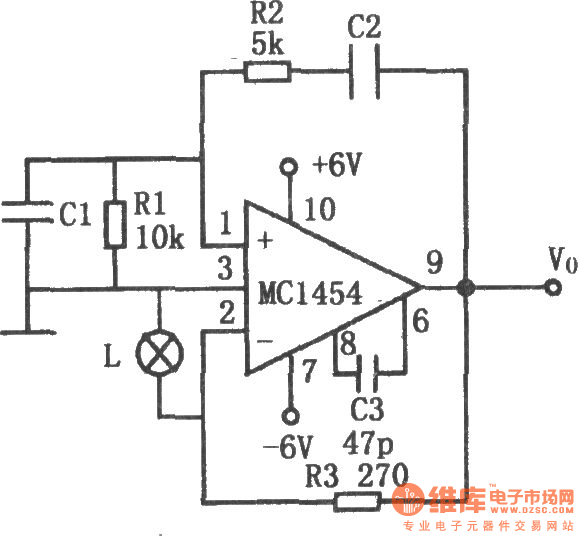
The chart shows the low power Wien bridge oscillator circuit. The circuit is characterized by little distortion when driving low impedance load and large capacitive loads. Operational amplifier used in the circuit could drive 8 ~ 10Ω load, the 10Ω load can provide 2 ~ 4V peak output voltage and the frequency is from 1Hz to 100kHz, distortion is less than 0.5%. Automatic gain control is achieved by a lamp L as the resistance of the bulb changing with the output voltage. Resistor R3 forms a negative feedback loop to determine the output signal amplitude. Capacitors C1 and C2, resistors R1 and R2 constitute a positive feedback. If the value of resistor R1 and the input impedance of the amplifier is equal, R2 = R1 / 2, C1 = C2, then the oscillation frequency; f0 = 1/2π,R1C1C3 is the high-frequency compensation capacitor. The following table lists the relationship between frequency and capacitance C1 (C2) .
Reprinted Url Of This Article:
http://www.seekic.com/circuit_diagram/Signal_Processing/Oscillator_Circuit/Low_power_Wien_bridge_oscillator_composed_of_MC1454.html
Print this Page | Comments | Reading(3)

Article Categories
power supply circuit
Amplifier Circuit
Basic Circuit
LED and Light Circuit
Sensor Circuit
Signal Processing
Electrical Equipment Circuit
Control Circuit
Remote Control Circuit
A/D-D/A Converter Circuit
Audio Circuit
Measuring and Test Circuit
Communication Circuit
Computer-Related Circuit
555 Circuit
Automotive Circuit
Repairing Circuit
Code: